You can create your own functions to use as shortcuts for more complicated chunks of code. For example, to create a function that makes an LED blink the number of times you specify as a parameter, with the LED pin also specified as a parameter, you could use the sketch below. This function is named blink, and you can call it during startup so that the Arduino L LED blinks five times after a reset.
➊ const int ledPin = 13;
➋ void setup()
{
pinMode(ledPin, OUTPUT);
➌ blink(ledPin, 5);
}
void loop() {}
➍ void blink(int pin, int n)
{
➎ for (int i = 0; i < n; i++)
{
digitalWrite(ledPin, HIGH);
delay(500);
digitalWrite(ledPin, LOW);
delay(500);
}
}
At ➊, we define the pin being used. The setup function at ➋ sets ledPin as an output and then calls the function blink ➌, passing it the relevant pin and the number of times to blink (5). The loop function is empty and does nothing, but the Arduino IDE insists that we include it even if it serves no purpose. If you don’t include it, you will get an error message when you install the program.
The blink function itself begins at ➍ with void. void indicates that the function does not return any value, so you cannot assign the result of calling that function to a variable, as you might want to do if the function performed some kind of calculation. Then follows the name of the function (blink) and the parameters the function takes, enclosed within parentheses and separated by commas. When you define a function, you must specify the type of each of the parameters (for example, whether they are int or float). In this case, both the pin (pin) and the number of times to blink (n) are int values. Lastly, at ➎, we have a for loop that repeats the digitalWrite and delay commands inside it n times.
That’s it for the software crash course. If you want to learn more about programming for Arduinos, visit http://www.arduino.cc/ before everyone at your Internet service provider becomes a zombie.
ASSEMBLING A SCREWSHIELD
Many of the projects in this book use a screwshield that fits over the Arduino sockets and allows you to connect wires to Arduino pins using screw terminals. Not all wires will fit into the normal Arduino sockets, but almost any thickness of wire will fit securely in a screw terminal and won’t come loose. There are various screwshields on the market, all with slightly different layouts. In this book, I use the popular model from Adafruit (the proto-screwshield, part number 196), which is provided as a kit that you have to solder together. There are lots of connections to make, but none of them are difficult. The component parts of the proto-screwshield are shown in Figure C-7.
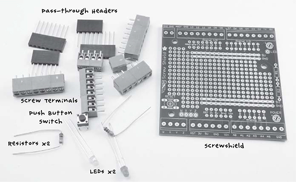
Figure C-7: The parts of Adafruit’s Proto-Screwshield
The screw terminals line the edge of the board and Arduino pass-through headers. The screwshield pass-through headers slot through the shield into the PCB. You can plug wires into these as you would in the Arduino Uno, and they have sockets on the top side so you can plug still another shield on top.
Of the two LEDs, one is a power LED that indicates when the board is powered up, and the other is for you to use in your build. You don’t have to solder either LED in place if you don’t need them. The push button is a reset switch, which can be useful as it’s hard to get at the Arduino’s reset button when the screwshield is in place. Again, it is by no means essential.
Figure C-8 shows the board being assembled.
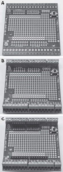
Figure C-8: Assembling the screwshield
To assemble the screwshield, follow these steps:
1. Solder the LEDs, resistors, and switch (assuming you want them) in place (Figure C-8a).
2. Put all the screw terminals in place along the outermost edges of the screwshield (Figure C-8b) and flip the board over to solder them on the underside of the PCB. Make sure they are the right way around so that the openings where the wires enter are facing outward, away from the board.
3. Push the pass-through headers through from the top of the board (Figure C-8c) and solder them. Notice that there are two rows of holes on each side of the board where they are able to go; place them in the outer sets of holes. The inner sets are used to wire things up to the pins on the central prototyping area of the board.
If you need a refresher on how to solder to a PCB, review “Soldering Basics” on page 230. With your components in place, make sure your solder joints look sound (also described in “Soldering Basics”). You should be ready to deploy this handy shield in all of your antizombie base defense endeavors and conserve precious solder for devices you intend to last a long time.
FURTHER RESOURCES
There are many great online resources and books that will tell you more about how to use the Arduino in your projects. Here are a few links to get you started:
• I have written a number of books on Arduino, including Programming Arduino: Getting Started with Sketches (Tab Books, 2012) and various Arduino project books. You can find a full list of my books at http://www.simonmonk.org/.
• Jeremy Blum, the technical editor of this book, has made a great series of introductory videos on the Arduino, which you can find here: https://www.youtube.com/playlist?list=PLA567CE235D39FA84.
• Jeremy also has written a great book on Arduino, called Exploring Arduino (Wiley, 2013).
• I have written a series of online Arduino lessons, the Adafruit “Learn Arduino” series, which you can find here: https://learn.adafruit.com/series/learn-arduino/.
INDEX
SYMBOLS AND NUMBERS
&& (and) operator, 257
* characters, 61
{ }, 250
== (double equal sign), 252
// (double slash), 250
|| (or) operator, 257
? command, 143, 144, 148
~ (tilde), 254
+5V pin, 150, 151
28 Days Later (film), 7
A
A (amperes), 23
AA batteries, 25
AC (alternating current), 23–24
adapters for converting to DC, 24
battery chargers powered by, 25
inverters for converting DC to, 24, 49–50
voltage range, on multimeters, 242
Adafruit “Learn Arduino” series, 261
Adafruit PIR module, 77
Adafruit’s ARDX Experimenters Kit for Arduino, 224
adapters
for converting AC to DC, 24
USB, 48–49
Address Resolution Protocol (ARP), 100
aircraft, 10
alarm function, 77, 130, 136
alarms. See PIR (passive infrared) detector; quiet fire alarm; temperature alarm; trip wire alarm
All_Sensors sketch, 76–77, 115, 129, 135, 142, 143, 144
alternating current. See AC (alternating current)
alternators, 25–26. See also bicycle generator
amperes (A), 23
analog inputs, on Arduino