The text preceded by a double slash (//) is called a comment. It’s not executable program code but rather a description of what’s happening at that point in the sketch.
Just after the words setup() and loop(), we have a { symbol. (Sometimes this is put on the same line as the preceding word and sometimes on the next line. Where it goes is just a matter of personal preference and has no effect on the running of the code.) The { symbol marks the start of a block of code, which ends with a corresponding } symbol. You’ll use curly brackets to group together all lines of code that belong to a particular function or other control structure.
The lines of code inside the setup function run just once, when power is applied to the Arduino or the Reset button is pressed. You use setup to perform all the tasks that need doing just once when the program starts. In Blink, the code inside the setup function just sets the LED pin as an output.
The commands inside the loop function will be run over and over again; in other words, when the last line inside loop has run, the first line will start again.
Now, let’s parse this sketch, starting from the top line.
CREATING VARIABLES AND CONSTANTS
Variables are a way of giving names to values; for example, the first line of Blink labels pin 13 led:
int led = 13;
This defines an int variable called led and gives it an initial value of 13, because 13 is the number of the Arduino pin that the L LED is connected to. The word int is short for integer and means that this variable returns a whole number without decimals.
In some of the book’s other sketches, variables like this, that define a specific pin to be used, are preceded by a const keyword:
const int led = 13;
The const keyword tells the Arduino IDE that the value of led is never going to change from 13, making it a constant. Assigning values this way results in slightly smaller and quicker sketches and is generally considered a good habit.
CONFIGURING DIGITAL OUTPUTS
The Blink sketch also shows a good example of a setting a pin up to be a digital output. Pin 13, having been defined as led, is configured as an output in the setup function by this line:
pinMode(led, OUTPUT);
As this only needs to be done once, it is placed inside the setup function. Once the pin is set as an output, it will stay an output until we tell it to be something else.
For it to blink, the LED needs to turn on and off repeatedly, so the code for this goes inside loop:
digitalWrite(led, HIGH); // turn the LED on (HIGH is the voltage level)
delay(1000); // wait for a second
digitalWrite(led, LOW); // turn the LED off by making the voltage LOW
delay(1000); // wait for a second
The command digitalWrite takes two parameters (pieces of data that the function needs to run), which are passed to the function inside parentheses and separated by a comma. The first parameter defines which Arduino pin to write to (in this case, pin 13, as specified by led), and the second parameter gives the value to be written to the pin. A value of HIGH sets the output to 5V, turning the LED on, and a value of LOW sets the pin to 0V, turning the LED off.
The delay function holds the parameter that defines how long the Arduino should continue with its current function. In this case, a value of 1000 delays the program for one second before changing the state of the LED.
CONFIGURING DIGITAL INPUTS
Digital pins can also be set as input pins using the pinMode command. The Blink sketch doesn’t do this, so here’s an example:
pinMode(7, INPUT)
This pinMode function sets pin 7 as an input. Just as with an output, you’ll rarely need to change the mode of a pin, so define input pins in the setup function.
Having set the pin as an input, you can then read the voltage at that pin, as in this example loop function:
loop()
{
if (digitalRead(7) == HIGH)
{
digitalWrite(led, LOW)
}
}
Here, the LED will be turned off if the input at pin 7 is read as HIGH at the time it is tested. The Arduino decides whether to turn the LED on with an if statement, which starts with the if command. Immediately after the word if is a condition. In this case, the condition is (digitalRead(7) == HIGH). The double equal sign (==) tells the machine to compare the two values on either side. In this case, if pin 7 is HIGH, then the block of code surrounded by { and } after the if will run; otherwise it won’t. We have already met the code to be run if the condition is true. This is the digitalWrite command to turn the LED on.
NOTE
Lining up the { and } makes it easier to see which } belongs to which {.
STABILIZING DIGITAL INPUTS WITH PULL-UP RESISTORS
The preceding example code in assumes that the digital input is definitely either high or low. A switch connected to a digital input can only close a connection. You’ll typically connect switches in such a way that when flipped, the digital input is connected to GND (0V). While the switch’s connection is open, the digital input is said to be floating. That means the input isn’t electrically connected to anything, but a floating input can still pick up electrical noise from the circuitry around it, causing the voltage on the pin to oscillate between high and low.
This behavior is undesirable because the code could be activated unexpectedly. To prevent input pins from floating, just add a pull-up resistor (Figure C-5). We use just such a resistor in “Project 6: PIR Zombie Detector” on page 72.
When the switch is open (as shown in Figure C-5), the resistor connects the input pin to a voltage source, pulling up the voltage at the input pin to 5V and holding it there. Pressing the button to close the switch overrides the weak pulling up of the input, connecting the digital input to GND instead.
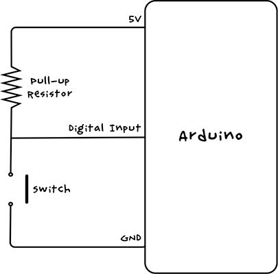
Figure C-5: Schematic for using a pull-up resistor with a digital input
Arduino inputs have built-in pull-up resistors of about 40 kΩ that you can enable as follows:
pinMode(switchPin, INPUT_PULLUP);
This example shows how you would set the pin mode of a digital input to be used with a switch using the Arduino pull-up resistor: just set the pin mode to INPUT_PULLUP rather than INPUT.
READING ANALOG INPUTS
Analog inputs allow you to measure a voltage between 0V and 5V on any of the A0 to A5 analog input pins on the Arduino. Unlike with digital inputs and outputs, you don’t need to include the pinMode command in setup when using an analog input.
You use analogRead to read the value of an analog input, and you supply the name of the pin you want to read as a parameter. Unlike digitalRead, analogRead returns a number rather than just true or false values. The returned number will be between 0 (0V) and 1,023 (5V). To convert the number into an applicable voltage, multiply the value by 5 and then divide it by 1,023, which amounts to dividing it by 204.6.
Here’s how you’d read an analog value and convert it in Arduino code:
int raw = analogRead(A0);
float volts = raw / 204.6;
The variable raw is an int (whole number) because the reading from an analog input is always a whole number. To scale the raw reading as a decimal number, the variable needs to be a float (floating point) type of variable.