WRITING TO ANALOG OUTPUTS
Digital outputs only allow you to turn a component (like an LED) on and off, but analog outputs allow you to control the level of power supplied to a component incrementally. This control allows you to, for example, control the brightness of an LED or the speed of a motor. This is used in “Project 20: Silent Haptic Communication with Arduino” on page 209 to reduce the power to the motor so that it doesn’t attract zombies by making too much noise.
Only the pins D3, D5, D6, D9, D10, or D11 are capable of being used as analog outputs. These pins are marked with a little tilde (~) beside the pin number on the Arduino.
To control an analog output, use the command analogWrite with a number between 0 and 255 as the parameter, as in the following line:
analogWrite(3, 127);
A value of 0 is 0V and fully off, while a value of 255 is 5V and fully on. In this example, we set the output of pin D3 to 127, which would be half power.
REPEATING CODE IN CONTROL LOOPS
Control loops (not to be confused with the loop function) allow you to repeat an action a set number of times or until some condition changes. There are two commands you can use for looping: for and while. You would use the for command for repeating something a fixed number of times and while for repeating something until a condition changes.
The following code makes an LED blink 10 times and then stops:
void setup() {
pinMode(led, OUTPUT);
for (int i = 0; i < 10; i++)
{
digitalWrite(led, HIGH);
delay(1000);
digitalWrite(led, LOW);
delay(1000);
}
void loop() {
}
HOW ANALOG OUTPUTS GENERATE VOLTAGES
It is tempting to think of an analog output as being capable of a voltage between 0V and 5V, and if you attach a voltmeter between an analog output pin and GND, the voltage will indeed seem to take on values between 0V and 5V as you change the parameter to analogWrite. In fact, things are a little more complex than that. This kind of output is using pulse width modulation (PWM). Figure C-6 shows what is really going on.
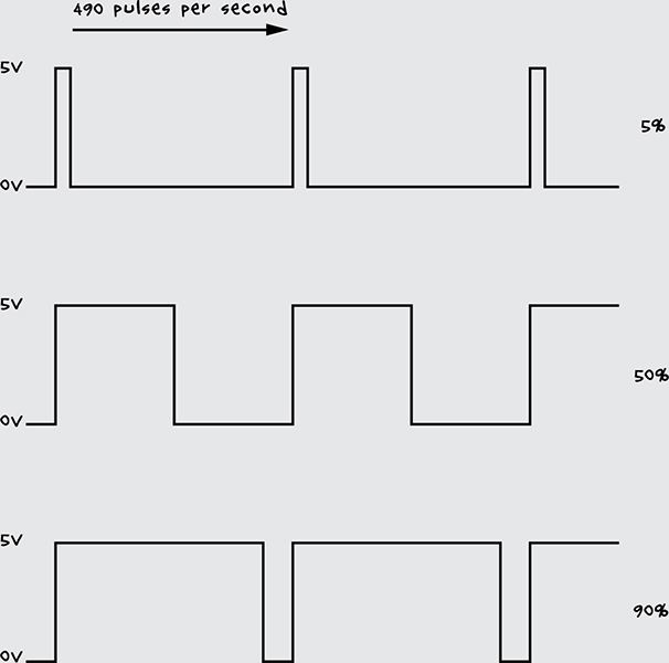
Figure C-6: Analog output’s pulse width modulation
An analog output pin generates 490 pulses per second with varied pulse widths. The larger the proportion of the time that the pulse stays high, the greater the power delivered to the output, and hence the brighter the LED or faster the motor.
A voltmeter reports this as a change in voltage because the voltmeter cannot respond fast enough and therefore does a kind of averaging (integration).
In this example, we place the blinking code in setup rather than loop, because loop would repeat the blink cycle immediately so the LED would not stop after 10 times.
If you wanted to keep an LED blinking as long as a button connected to a digital input was pressed, you would use a while command:
➊ while (digitalRead(9) == LOW)
{
digitalWrite(led, HIGH);
delay(1000);
digitalWrite(led, LOW);
delay(1000);
}
This code says that while pin 9 detects that a button is being pressed ➊, the LED should be lit.
SETTING TWO CONDITIONS WITH IF/ELSE
In “Configuring Digital Outputs” on page 251, we used an if command to tell the Arduino IDE to do something if a certain condition was met. You can also use if in conjunction with the else command to instruct the IDE to perform one set of code if the condition is true and a different set of commands if it is false. Here’s an example:
if (analogRead(A0) > 500)
{
digitalWrite(led, HIGH);
}
else
{
digitalWrite(led, LOW);
}
This if statement turns the led pin on if an analog reading is greater than 500 or off if the reading is less than or equal to 500.
MAKING LOGICAL COMPARISONS
So far we have used two types of comparison: == (equal to) and > (greater than). Here are some more comparisons you can make:
<= less than or equal to
>= greater than or equal to
!= not equal to
You can also make more complicated comparisons using logical operators like && (and) and || (or). For example, to turn an LED on if a reading is between 300 and 400, you could write the following:
int reading = analogRead(A0);
if ((reading >= 300) && (reading <= 400))
{
digitalWrite(led, HIGH);
}
{
digitalWrite(led, LOW);
}
In English, this code might read, “If the reading is greater than or equal to 300 and the reading is less than or equal to 400, then turn the LED on.” Since we’re using the && operator to specify that both conditions must be true, if either condition is not met, the LED remains dark.
GROUPING CODE INTO FUNCTIONS
Functions can be confusing if you’re new to programming. Functions are best thought of as ways to group together lines of code and give them a name so that the block of code is easy to use over and over again.
Built-in functions such as digitalWrite are more complicated than they first seem. Here is the code for the digitalWrite function:
void digitalWrite(uint8_t pin, uint8_t val)
{
uint8_t timer = digitalPinToTimer(pin);
uint8_t bit = digitalPinToBitMask(pin);
uint8_t port = digitalPinToPort(pin);
volatile uint8_t *out;
if (port == NOT_A_PIN) return;
// If the pin that support PWM output, we need to turn it off
// before doing a digital write.
if (timer != NOT_ON_TIMER) turnOffPWM(timer);
out = portOutputRegister(port);
uint8_t oldSREG = SREG;
cli();
if (val == LOW) {
*out &= ~bit;
} else {
*out |= bit;
}
SREG = oldSREG;
}
Since someone already wrote the digitalWrite function, we don’t have to worry about what all this code does; we can just be glad that we don’t have to type it all out every time we want to change pin from high to low. By giving that big chunk of code a name, we can just call the name to use this code.