3. Connect the positive test lead of the meter to the positive side of the battery and the negative test lead to the positive voltage connection of the lead to the Arduino.
As shown, the multimeter is effectively intercepting the current flowing through the test leads in order to measure the current.
MEASURING RESISTANCE
“Resistor Color Codes” on page 225 includes a guide to identifying the values of resistors from their color stripes. Another way to find the value of a resistor is to measure it using a multimeter. Just set the meter to one of its resistance ranges and then touch the two test leads to either side of the resistor (Figure B-13).
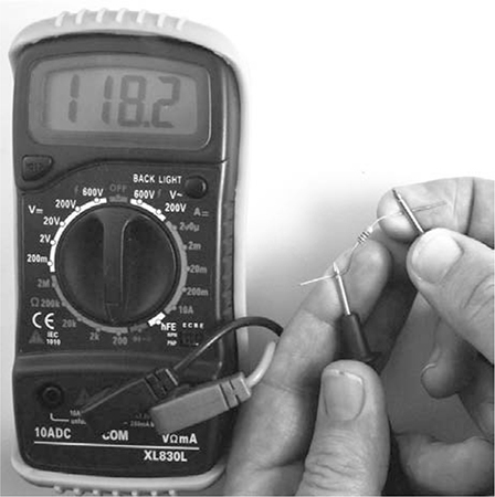
Figure B-13: Measuring resistance with a multimeter
In this case, the resistor is measured as 118.2 Ω. The resistor’s nominal value, according to the stripes, is 120 Ω. This slight discrepancy is perfectly normal. Neither the multimeter nor the resistor itself will be completely accurate.
NOTE
Some meters also have one or more capacitance ranges, which you can use to measure the value of capacitors in the same way.
CONTINUITY TESTING
Most multimeters have a Continuity or Buzzer mode, selectable from the range knob. When the multimeter is set to continuity, a buzzer on the multimeter sounds if the two test leads are touched together. The buzzer should also sound when the leads are connected by something with low resistance, like a wire, PCB track, or dubious solder joint.
This function may not sound very useful, but it is actually invaluable. It allows you to test fuses as well as suspect wires that look okay but may have a break beneath the insulation. It is also good for testing switches. Just touch the leads the switch contacts, and if the multimeter buzzes when you flip the switch, then all is well. Similarly, to test a fuse, first touch the test leads together to hear the beep and make sure the multimeter is working and then touch the leads to either end of the fuse. If the meter doesn’t work, then the fuse has blown.
BELLS AND WHISTLES
The multimeter features I’ve already described will cover pretty much any test you might need to perform on a circuit in this book. However, even a cheap multimeter, like the one shown here, has some other useful settings:
AC voltage and current A separate set of ranges are needed for AC because it swings both positive and negative, making its average value zero, so the meter will convert the AC to DC internally before giving a reading if one of these ranges is selected.
HFE This range will measure the gain (current amplification factor) of a transistor plugged into the special transistor socket. This is also a quick way to see whether a transistor is dead.
If you buy a more expensive multimeter, you will find it has even more bells and whistles:
Frequency measurement Measures the frequency of a signal. You could, for example, use this to find the frequency of the buzzer on the smoke alarm in “Project 11: Quiet Fire Alarm” on page 120.
Temperature This function requires a special thermocouple probe. It’s useful as a general thermometer and is especially valuable as a way to see if components are getting dangerously hot.
Capacitance This setting is useful for comparing the capacitance written on the side of a capacitor with its actual capacitance. Electrolytic capacitors are notoriously unreliable as they get older. They often degrade into a zombie-like state, causing problems in many kinds of electronic equipment.
Backlight Lights the screen on your multimeter, which is useful if you are trying to use the multimeter to work out why the lights in your base have gone out!
Auto power off Very handy if, like me, you tend to forget to switch things off. You never know when you’ll find more batteries, after all.
Your multimeter will be one of your most useful tools, so get familiar with it. That way, should you have to use it under pressure as the zombies close in, you won’t have to waste valuable time consulting the manual.
C
ARDUINO PRIMER

Arduino microcontroller boards are perfectly suited to a postapocalyptic world. They’re robust, they’re reliable, and they use very little power. If you’re new to Arduino, this appendix will get you started with this great little board so you can begin to make your end-of-the-world preparations now and greatly enhance your chances of survival.
WHAT IS AN ARDUINO?
There are various types of Arduino board, but by far the most common is the Arduino Uno, and this is the one used for all the projects in this book (see Figure C-1).
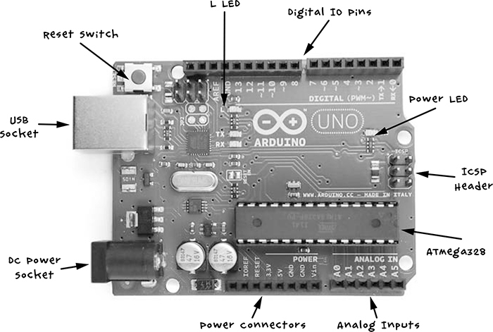
Figure C-1: An Arduino Uno R3
The Arduino Uno shown in Figure C-1 is a revision 3 (R3) board, which is the latest at the time of writing. We’ll have a look at each of the components and their uses.
Let’s start our tour with the USB socket. This serves several purposes: it can be used to provide power to the Arduino or to connect the Arduino to your computer for programming. It can also serve as a communications link to other computers, as in “Project 13: A Raspberry Pi Control Center” on page 140 where it sends data from the Arduino to a Raspberry Pi. The little red button on the Arduino is the Reset button. Pressing it will cause the program that is installed on the Arduino to restart.
The connection sockets along both the top and bottom edges of the Arduino are where you attach electronics. On the top side of Figure C-1 are digital input and output pins, numbered 0 to 13 and configurable as either inputs or outputs. Inputs read messages coming in; for example, if you connect a switch to a digital input, the input will detect whether the switch is pressed. Outputs send information or power out; if you connect an LED to a digital output, you can turn it on by switching the output from low to high. In fact, one LED, called the L LED, is built onto the board and connected to digital pin 13.
On the right, the power LED indicates whether the board is powered. The ICSP (In-Circuit Serial Programming) header is only for advanced programming of the Arduino, and most casual users of Arduino will never use it.
The ATMega328 is a microcontroller integrated circuit (IC) and the brains of the Arduino. The chip contains 32KB of flash memory, where you store the program you want the Arduino to run.
On the bottom right of Figure C-1 is a row of analog input pins labeled A0 to A5. Digital inputs can only tell whether something is on or off, but analog inputs can actually measure the voltage at the pin, as long as the voltage is between 0V and 5V. Analog input pins could be used, for example, to measure voltage from a temperature sensor like the one used in “Project 12: Temperature Alarm” on page 131.
The final row of sockets provides miscellaneous power connections. In “Project 4: Battery Monitor” on page 53, we use Vin (volts in) to provide power to the Arduino; 5V and GND (or ground), which means 0V, are also power connections that you will need when connecting external electronics.
At the bottom left, we have a DC power jack, which is another power connection. This can accept anything between 7V and 12V DC. The Arduino will automatically accept power from the USB socket and power from the DC connector or Vin socket, too.
ARDUINO SOFTWARE
The Arduino might not be what you would expect from a computer. It has no operating system and no keyboard, monitor, or mouse. This is, of course, good news for the survivor who needs to travel light. And while you can reprogram an Arduino as many times as you like, it also only ever runs a single program (called a sketch) at a time. To program the Arduino, you must have the Arduino IDE software installed on your normal computer, so we’ll first cover installation and then talk about writing programs.