Finally, coil the intertwined wires into a tight ball (Figure B-2c) and wrap the whole thing in electrical tape or heatshrink tubing (see “Using Heatshrink” on page 235). You can also use pliers to really tighten up the joint.
If you have soldering equipment, then you can make the connection mechanically stronger and more electrically reliable by heating the little knot with a soldering iron and feeding solder into it, as I describe in the next section.
If you want to know how NASA does it, take a look at this link: http://makezine.com/2012/02/28/how-to-splice-wire-to-nasa-standards/.
SOLDERING BASICS
Soldering is much easier than it looks, and you don’t need to spend a lot of money on a fancy soldering station. During an apocalypse, your options will be limited, but a basic starter kit (see Figure B-3) will work just fine.
You can find basic soldering kits at an auto parts store or even at some hardware stores. If you are buying in advance of the apocalypse, then Adafruit sells a great starter kit (product 136) that also includes a multimeter, hookup wire, and various other useful bits and bobs.
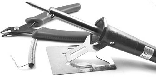
Figure B-3: A basic soldering kit
There are lots of accessories and tools that can make soldering quicker, but these are by no means essential. Here’s all you really need:
A soldering iron Look for an iron with a power rating of 30W or more, with a fine tip (say 1/25 inch, or 1 mm). Before the zombie apocalypse, just buy one that’s AC powered. To prepare, you could also buy a soldering iron that runs on 12V DC and keep it with your emergency supplies; that way, you’ll have an iron you can power from a car battery. These soldering irons, intended for working on the electrical components of cars, are quite common.
Solder If you buy a soldering kit, it will probably come with a coil of solder. Solder comes in two flavors: leaded and lead-free. Leaded solder melts at a lower temperature and is generally easier to use than lead-free solder. But please don’t eat either, no matter how desperate your food situation becomes.
Snips You’ll need a good pair of wire cutters to cut wires close to the surface of a PCB and for stripping wire.
A damp sponge or cloth Any old sponge will do. You’ll use it to wipe the tip of the iron when there’s excess solder.
WARNING
Soldering irons get hot. In fact, they get really hot, much hotter than the maximum temperature of your kitchen oven. So it goes without saying that if you touch the hot end of a soldering iron, you’ll get a serious burn. This is not an activity for unsupervised children. Similarly, lead is a toxic element that is not at all good for you, so you may prefer to use lead-free solder, despite it being a little harder to work with.
JOINING WIRES WITH SOLDER
To join together two wires with solder, start by following the instructions in “Joining Wires by Twisting” on page 229. Then, you can solder the joint. The trick with soldering is to always make the solder flow into the thing you’re soldering; Figure B-4 shows solder flowing into the ball of wires from Figure B-2c.
Many beginners make the mistake of creating a blob of solder on the tip of the iron and then blobbing it onto the wire. This usually results in poor quality dry joints that may look okay but will fail quickly and, before they fall apart, may not make good contact with the wire. Therefore, you’ll want to heat the wire you want to solder before you touch the solder to it.
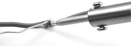
Figure B-4: Running solder into the joined wires
With that in mind, you can join your twisted wires as follows:
1. Turn your iron on and leave it to heat up. If your kit didn’t come with a stand for the soldering iron, make sure that you prop it somewhere safe so that the hot end is not touching anything.
2. Touch the end of the solder to the tip of the iron to see if it is hot. If it immediately melts and flows over the tip of the iron, then the iron is ready.
3. If the tip of the iron is not shiny and bright after this, then wipe it on a wet sponge. This makes a great sizzling noise! Repeat the previous step to tin the tip of the iron with solder. Tinning just means coating a wire or the tip of your iron with solder by heating it up and then pushing the solder onto it.
4. Press the tip of the soldering iron against the little knot of wires and leave it there for perhaps three or four seconds. Then, with the soldering iron still pressed to the knot, push the end of the solder onto the knot. The solder should flow into the knot. If your solder isn’t flowing well, it sometimes helps to feed a bit more solder to the joint, as solder contains cores of rosin flux, which helps the solder to liquefy.
5. Keep feeding the solder in until the whole knot of wires is coated in solder.
6. Remove the tip of your solder thread from the joint and replace the iron on its stand. Make sure that the wires don’t move while you give them 10 or 20 seconds to cool down.
You can also insulate your soldered connection with electrical tape or with heatshrink, as described in “Using Heatshrink” on page 235. If you plan to do this, then you can make a neater joint by soldering the wires side to side, without twisting them together (Figure B-5a–e).
After stripping the ends of the wires (Figure B-5a), tin them with solder (Figure B-5b). If the wire is stranded, the solder should flow between the strands that make up the wire.
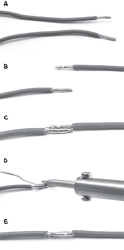
Figure B-5: Soldering wires together without twisting them first
Now, lay the wires next to each other (Figure B-5c), heat the wires, and run solder into the valley they make (Figure B-5d). The end result should be a nice, even joined pair of wires (Figure B-5e).
SOLDERING A PCB
Wires are easier to scavenge than complete circuits, but being able to solder to a printed circuit board (PCB) will certainly serve you well during an apocalypse. For example, quite a few of the projects in this book use a screwshield that requires a bit of soldering to put together. Fortunately, the screwshield is a PCB with lots of convenient metal pads that are made for soldering. If you successfully followed the steps described in “Joining Wires with Solder” on page 231, then you shouldn’t have any problems soldering a PCB.
When attaching components to a PCB, the basic idea is that you push a component’s legs through from the top, flip the PCB over, solder the leads to their solder pads, and snip off the excess wire. Figure B-6 shows a component lead being soldered onto a screwshield.
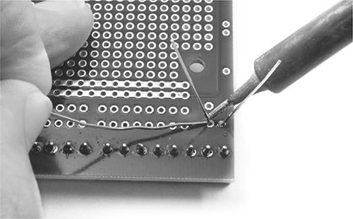
Figure B-6: Soldering a component leg to a PCB
As with all soldering, the trick is to apply the solder to the thing being heated up rather than to the soldering iron, so heat the component leg and touch solder to it. You’ll often get the best results by giving the soldering iron a second or two to heat the component lead and solder pad before you apply the solder to the junction of the soldering iron tip and the component lead. Figure B-7 shows examples of two solder joints, one bad and one good.
The solder joint on the left is best described as “blobby,” and it’s a result of allowing a glob of solder to form on the tip of the iron and then “blobbing” it onto the PCB. The solder joint on the right is close to perfect. See how the whole pad is covered in solder, flowing all the way around the component lead and forming a very gentle little hill of a meniscus.