Figure 11-8: The underside of the protoshield
Double-check everything very carefully to make sure there are no accidental solder connections and that every wire makes the correct connection.
STEP 4: ATTACH THE VIBRATION MOTOR
Glue the motor to the top of the protoshield, being careful not to get glue on the rotating bit at the front of the motor. The leads are quite fine, so it’s better to solder them to the top of the board rather than through a hole. Figure 11-9 shows the motor glued in place and the leads soldered to the protoshield.
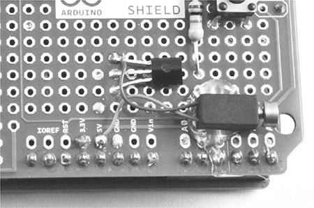
Figure 11-9: Attaching the vibration motor
STEP 5: REPEAT FOR THE OTHER HANDSET
Having built one handset, do the whole lot again for its partner.
STEP 6: PLACING IT INTO AN ENCLOSURE
You may want to scavenge for some small plastic boxes to contain the handsets. Alternatively, you might prefer to go postapocalypse chic and just tape the battery to the Arduino and protoshield, leaving the battery clip accessible as a rudimentary switch.
SOFTWARE
All the source code for this book is available from http://www.nostarch.com/zombies/. See Appendix C for instructions on installing the Arduino sketch for this project, which is called Project_20_Haptic_Communicator.
This project uses a community-maintained Arduino library called Mirf. This library provides an easy-to-use wrapper around the Serial Peripheral Interface (SPI) serial interface to the NRF24 radio module, allowing the Arduino to communicate with the module. The Mirf library must be downloaded from the Internet, which is another good reason to make this project before the outbreak spreads too far. Download the ZIP file for the library from http://playground.arduino.cc/InterfacingWithHardware/Nrf24L01.
Extract the ZIP file and copy the whole Mirf folder into My Documents\Arduino\Libraries if you’re using Windows or Documents/Arduino/libraries if you’re using a Mac or Linux. Note that if the libraries folder doesn’t exist within the Arduino directory, you’ll need to create it before copying.
The Arduino IDE won’t recognize the new library until you restart it, so after copying the library folder, save anything you’re working on, quit the IDE, and restart. Next, open the sketch file for this project and upload it to both Arduinos, one after the other. The sketch starts by importing three libraries:
#include <SPI.h>
#include <Mirf.h>
#include <MirfHardwareSpiDriver.h>
The SPI library is part of the Arduino IDE distribution and simplifies communication with devices using SPI. The MirfHardwareSpiDriver library is also used in the sketch.
Next, three constants are defined:
const int numberOfSends = 3;
const int buzzerPin = 5;
const int switchPin = 2;
The range of wireless communication can be extended by sending the “button pressed” message several times, so that at the edge of the range, only one of the messages has to get through. The constant numberOfSends defines how many times each message should be sent. This is followed by pin definitions for the buzzer and switch pins.
The next constant (buzzerVolume) specifies the analogWrite value for the vibration motor:
const int buzzerVolume = 100; // Keep less than 153 for 3V!
const int buzzMinDuration = 20;
If you are using a 3V motor, it is important that the analogWrite value does not exceed 153; a value of 153 will deliver power equivalent to a 3V supply to the motor, and more power would overload it. Reducing this value will make your buzzer quieter. The buzzMinDuration constant specifies the minimum duration for a buzz in milliseconds. This is important because too short a buzz may not be noticed.
The global byte data array contains a 4-byte message to be sent whenever the button is pressed:
byte data[] = {0x54, 0x12, 0x01, 0x00};
The first three values in this array are chosen as being unique for the pair of haptic communicators. When a message is received, they are checked to see whether they match. This ensures that the communicator has received a real message and not just noise. It also means that you could set up a second pair of devices using different values, and the new pair would not interfere with this pair. Depending on the group dynamics in your band of survivors, you might want to communicate with one person in some situations (“Come save me!”) and another person in other situations (“If you show up now, I bet the zombie will eat your brains and not mine”).
The fourth byte is not used in this project, but it’s there in case you would like the button-press messages to send a parameter. You could, for example, add a second button to the communicator for emergencies that sends a different value in this byte, which could then be read at the receiving end.
Next is the setup function:
void setup()
{
analogWrite(buzzerPin, 0);
pinMode(switchPin, INPUT_PULLUP);
Mirf.spi = &MirfHardwareSpi;
Mirf.init();
listenMode();
Mirf.payload = 4;
Mirf.config();
}
This function starts by making sure the buzzer is off at analogWrite. Then it sets the mode of the switchPin to an input with the internal pull-up resistor enabled (see “Stabilizing Digital Inputs with Pull-up Resistors” on page 252 for more information on pull-up resistors). The radio module is then initialized and put into listen mode, waiting to receive a message.
Next comes the loop function:
void loop()
{
if (!Mirf.isSending() && Mirf.dataReady())
{
Mirf.getData(data);
checkForBuzz();
}
if (digitalRead(switchPin) == LOW)
{
sendBuzz();
}
}
This starts with an if statement that first checks whether the module is itself sending a message. It then checks whether there is data ready to be read, and it reads the message over the radio. Once the message is read, the function checkForBuzz is called to check that the message is legitimate before buzzing the vibration motor.
The loop function finally checks for a button press on this end and responds to a button press by calling the sendBuzz function.
Now, let’s look at the other functions defined in this sketch, starting with listenMode and sendMode:
void listenMode()
{
Mirf.setRADDR((byte *)"serv1");
}
void sendMode()
{
Mirf.setRADDR((byte *)"clie1");
}
The listenMode function puts the radio module into listening mode by setting its receive address to "serv1". The sendMode function puts the radio module into sending mode by setting its receive address to "clie1". We call both the listenMode function and the sendMode function inside sendBuzz, which gets called in the loop function’s last if statement.