2 x Arduino Protoshield PCB
eBay (Arduino code: A000077)
Header pins 64 way in total (for 2 handsets)
Adafruit (392), eBay
2 x Arduino 9V battery leads
Adafruit (80), eBay
2 x PP3 batteries
Hardware store
2 x 1 kΩ resistor
Mouser (293-1k-RC)
2 x 2N3904 NPN bipolar transistor
Adafruit (756)
2 x 5V or 3V vibration motor
eBay
2 x tactile push switch
Adafruit (504)
2 x NRF24 RF modules
eBay
Stranded wire
Insulated solid-core wire for making PCB connections
You might also want to enclose your communicators in plastic boxes to protect them from the elements. If you choose to do so, then you will need to find something big enough to contain the Arduino, protoshield, and battery. It will also need a hole so that you can press the button and add an on/off switch.
Electronically, this is probably the most complicated project so far. You might struggle to find all the parts after a zombie apocalypse, as some, like the vibration motors and the RF modules, are best bought off eBay or Amazon. So make this project now, before the postal service un-dies. Vibration motors can also be scavenged from cellphones.
CONSTRUCTION
These instructions will tell you how to make one haptic module, and Figure 11-3 shows the schematic for one communicator. Of course, to communicate with someone else, you will need to make two devices.
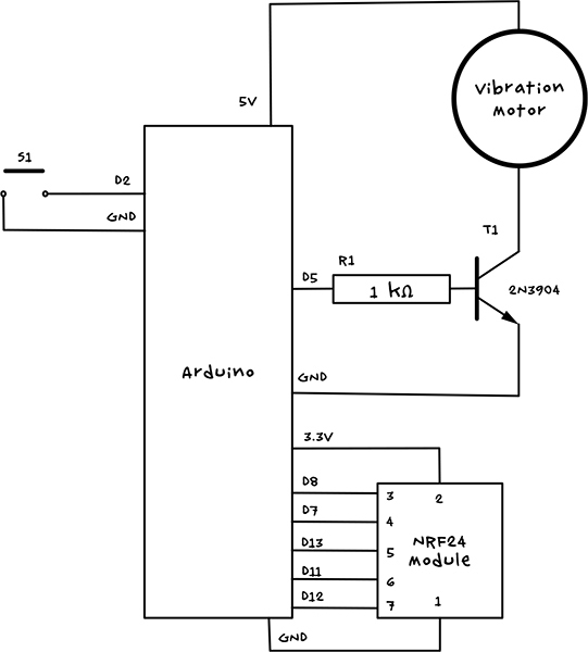
Figure 11-3: The schematic for one haptic communicator
Pin 2 of the Arduino will be set up as a digital input with internal pullup resistor enabled, connected to the push button S1. When the button is pressed, the Arduino will control the NRF24 radio module to send a message to the other handset, activating its vibration motor.
The vibration motor is controlled from pin D5 of the Arduino. We use a transistor (T1) because the motor uses more current than the Arduino output can cope with by itself, and the 5V supply is used because the 3V supply cannot provide enough current. Pin D5 is controlled as an analog output to manage the level of vibration with the software, keeping the device as quiet as possible; this also prevents the motor from burning out, as most vibration motors are 3V rather than the 5V the Arduino usually uses.
Note that strictly speaking, the motor should be accompanied by a diode to protect the Arduino from current spikes from the motor, but a little testing with one of these tiny motors showed that a very minimal amount of noise was added to the Arduino supply rails. So for the sake of keeping things simple the normal diode was omitted.
This project uses a protoshield rather than the screwshields used in most of the projects in this book. A protoshield is like a screwshield but without its screw terminals and hence is a bit cheaper and smaller.
STEP 1: ASSEMBLE THE PROTOSHIELD
Protoshields sometimes come with a full set of extra components, such as reset switches and header pins, but for this project you don’t want glowing power LEDs that might attract unwanted attention. Therefore, it’s better (and cheaper) to buy the bare Protoshield PCB and some headers.
Solder the header pins to the outermost rows of holes on each side of the PCB. A good way to keep the header pins straight is to put them into an Arduino and then put the Protoshield PCB on top of the headers. When all the pins are attached, the protoshield should look something like Figure 11-4.
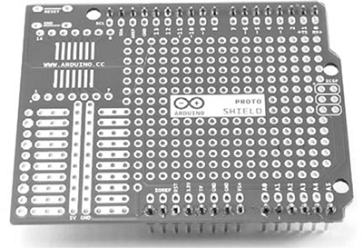
Figure 11-4: A protoshield with header pins attached
STEP 2: FIX THE COMPONENTS IN POSITION
Use Figure 11-5 as a reference for the location of the components. All the connections to the NRF24 module are to the 2×4 header on the right of the module’s PCB. Don’t solder the vibration motor just yet; it will need to be glued in place first as the leads are a bit delicate.
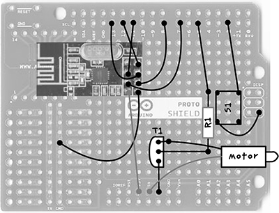
Figure 11-5: The protoshield layout, where R1 is the resistor, S1 is the switch, T1 is the transistor, and the dark rectangle at the top left is the NRF24
Apart from the two wires coming from the motor, the dark lines going to various solder pads in Figure 11-5 represent connections you’ll make on the underside of the board. The header pins of the NRF24 module fit through the holes in the protoshield, so place that now and solder it to the pads beneath. Do not clip the excess pin lengths off but instead gently splay them out after soldering; this will make it easier to connect them up later. Note that one pin on the NRF24 module is not used.
The transistor has one curved side. It is important that this goes onto the protoshield the right way around, with the curved side pointing left toward the NRF24 (use Figure 11-4 as a guide). Leave about 1/3 inches (about 7.5 mm) of the transistor lead on the top side of the screwshield and fold it down (Figure 11-5) to solder.
The switch has contacts that are on a rectangular grid, four holes long one way and three holes the other. Make sure the switch goes the right way around (Figure 11-4) so that it is longer vertically.
Do not clip off any wires yet, as these can be used to link up the components on the underside of the board. When all the components have been fixed in place, the board should look something like Figure 11-6.
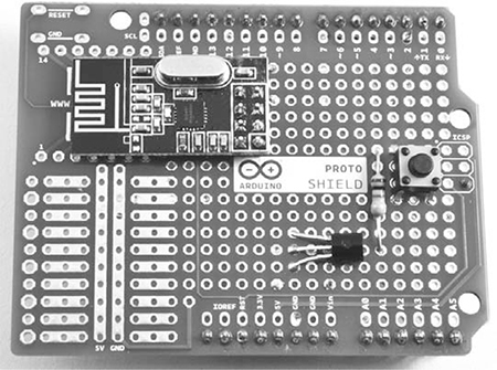
Figure 11-6: The components attached to the protoshield
STEP 3: WIRE THE UNDERSIDE OF THE BOARD
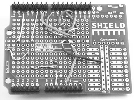
This step is the fiddliest, so take care with it. All the components need to be connected on the underside of the board (Figure 11-5). Of course, when the board is flipped over, everything is reversed. In Figure 11-7, I’ve transposed Figure 11-5 to show the underside of the board for you to work from.
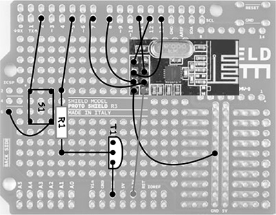
Figure 11-7: Wiring diagram from the underside of the protoshield
Figure 11-7 marks the positions of the components so that you can orient yourself, but remember that this is the underside of the board, so the components are actually on the other side of the protoshield.
Many of the connecting wires cross over each other, so use insulated solid-core wire. When everything is connected, the underside of the board should look like Figure 11-8.