USING THE RADIO SCANNER
When you first turn everything on, you should hear static. After five seconds or so, the scan LED will glow very dimly, and the radio will scan for its first station. After five more seconds, it will move on to the next station, and so on, until you identify a human friend. Remember: safety in numbers—not hordes.
PROJECT 19: ARDUINO MORSE CODE BEACON
Morse code is a 19th-century invention that allows you to send messages using a series of long or short pulses of light or sound. Each letter of the alphabet is made up of dots and dashes, where a dot is a short pulse and a dash is a long pulse (three times longer than a dot). For example, the letter z is represented as this:
z
--..
And the word zombie would be this:
zombie
--.. --- -- -... .. .
Morse code uses shorter sequences of dashes and dots for the more commonly used letters, so e, as the most common letter used in the English language, is just a single dot. If you are interested, you can search online for the complete Morse code, though the software in this project will translate your message into Morse code for you. Take a look at the code for a table of Morse codes.
This Arduino-based project uses 12V LED lamps, like those you used back in “Project 3: LED Lighting” on page 49, to flash a message to any other survivors in visual range. It’s especially effective at night. Figure 10-11 shows the finished project.
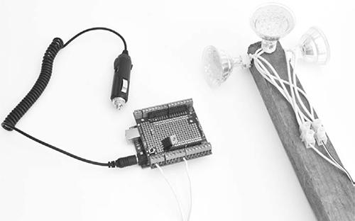
Figure 10-11: A Morse code beacon
WHAT YOU WILL NEED
To make this project, you will need the following parts:
ITEMS
NOTES
SOURCE
Arduino Uno R3
Adafruit, Fry’s (7224833), Sparkfun
Adafruit (196)
Mouser (293-1k-RC)
FQP33N10 MOSFET
Adafruit (355)
12V 3W
Hardware store
Sockets with trailing leads
Hardware store
2-way terminal block
Home Depot, Lowe’s, Menards
DC power jack with flying leads or 12V cigarette lighter adapter
DC power supply
Bell cable (or other cable)
It is best to use a fresh Arduino and screwshield for this project, both because it will be situated away from your main setup and because your screwshield from previous projects is probably pretty full by now. This project will be powered by its own solar power supply and battery (refer to “Project 1: Solar Recharging” on page 26).
I used three LED lights, but if you want more lamps, just add more in parallel. The transistor used to switch the lights is capable of switching up to 20W of lighting but only with a heatsink, so your combined wattage should be kept below 10W. If you made “Project 3: LED Lighting” on page 49, I would just use the same LEDs.
CONSTRUCTION
The layout for the screwshield and wiring schematic are shown in Figure 10-12.
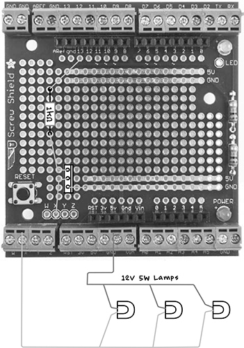
Figure 10-12: Screwshield layout and wiring schematic for the Morse code beacon
STEP 1: ASSEMBLE THE SCREWSHIELD
Assemble the screwshield following the instructions in “Assembling a Screwshield” on page 259.
STEP 2: SOLDER THE COMPONENTS ONTO THE SCREWSHIELD
You only need to solder two components for this project: a resistor and metal oxide semiconductor field effect transistor (MOSFET). MOSFETs are great for switching fairly high-power loads quickly.
Solder the resistor and transistor in place according to the circuit schematic. When soldering the transistor, make sure you place it so that the metal tab faces to the right (Figure 10-12). When the components are soldered into place, the assembly should like Figure 10-13.
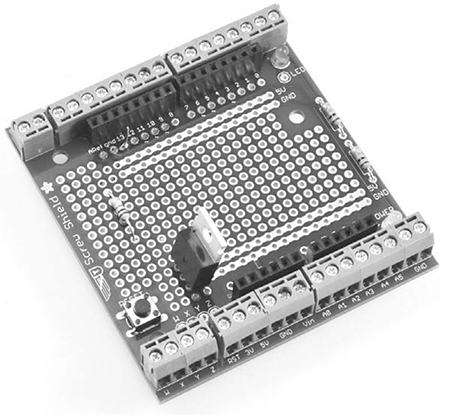
Figure 10-13: The top of the screwshield
STEP 3: WIRE THE UNDERSIDE OF THE SCREWSHIELD
Once the components are secured in place, use their excess leads to make the connections on the underside (Figure 10-14). Before soldering the resistor lead that connects to pin 13 on the Arduino, add some insulation to avoid causing short circuits with the 5V and GND tracks it crosses over.
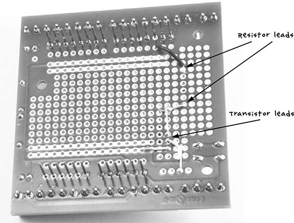
Figure 10-14: The underside of the screwshield
STEP 4: CONNECT THE LAMPS
If you want to keep this simple, you can just use a single LED lamp. For a wider range of visibility, however, connect a few LED lamps and point them in different directions (Figure 10-15).
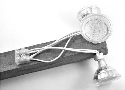
Figure 10-15: The lamp assembly
In Figure 10-15, I’ve fixed three lamp sockets to a bit of wood and connected all three 12V LED lamps to the terminal block. Lamps of this type usually include a circuit that allows the wires to be connected any way around, but if your modules have a polarity marked on them with a + and –, you need to make sure all the + connections are connected to one terminal of the terminal block and the – connections go to the other. The lamp holders will have holes allowing them to be attached to the wood with screws.
STEP 5: FINAL WIRING
Use some bell cable or other wire to connect the lamp assembly to the X and Vin terminals on the screwshield. Stranded wire is best, as it’s less liable to break. Make this wire as long as you need it (but above 50 ft, or 15 m, there might be some reduction in brightness): you may want to site the lamp assembly high up outside, to make it easier for people to see your message, while leaving the Arduino in the safety of your bunker. Remember to waterproof the lamp assembly—sealing it in a transparent plastic bag will do the trick.
To connect power to the Arduino, use either a cigarette lighter adapter or a custom lead using alligator clips and a barrel jack plug with flying leads to connect the Arduino to a 12V solar power supply or battery. Note that this project requires 12V for the lamps, so you cannot use a 5V USB lead to power the Arduino.
SOFTWARE
All the source code for this book is available via http://www.nostarch.com/zombies/. See Appendix C for instructions on installing the Arduino sketch. The Arduino sketch for this project is called Project_19_Morse_Beacon.