Figure 10-6: Radio scanner wiring diagram. The numbers 15 and 16 on the SC1088 radio indicate pin numbers of the chip.
The “tune” and “reset” pins of the SC1088 IC are designed to be connected to momentary pushbuttons that short these pins to the chip’s 3V supply rail. You can see this configuration in the datasheet’s reference schematic. When pushbuttons are not shorting the input pins to the supply rail, they are pulled down to ground by variable resistances that are set inside the chip. We can emulate the functionality of the pushbutton by connecting these pins to ~3V when we want to simulate a button push, and by leaving the pin floating (not being driven high or low) when we want to simulate a button waiting to be pressed. To make the pin float, we can set the Arduino pin that is driving it to an input. When acting as an input, an I/O pin is said to be high impedance, meaning that the pin looks like an open circuit to anything that is attached to it.
To convert the 5V of the Arduino output pins to 3V, we place red LEDs between the Arduino pin and the SC1088. These drop the 5V to about 3.3V, the same level as supplied to the chip. The LEDs will also glow very slightly when activated, letting you know when the project is in operation.
STEP 1: DISASSEMBLE THE RADIO
First, take the radio apart. How to do this will depend on how your radio is put together. For mine, I just undid two screws and the whole thing came apart. Figure 10-7a shows the radio in its original state and 10-7b after removal of the case.
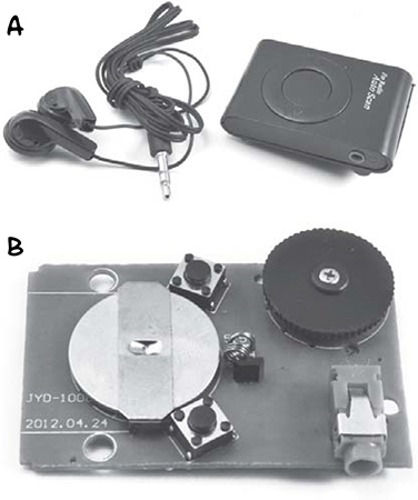
Figure 10-7: taking the radio apart
Take the button cell battery out because we are going to use the Arduino to supply power to the radio.
STEP 2: IDENTIFY THE CONNECTION POINTS
Now we need to identify the points where we need to attach wires and LED leads. Figure 10-8 shows the underside of the radio’s circuit board.
Start by identifying the location of the Scan and Reset switches. The pins for these will form a rectangle. The pins are connected in pairs, so both of the solder points labeled A are actually connected, as are the pair of points labeled B.
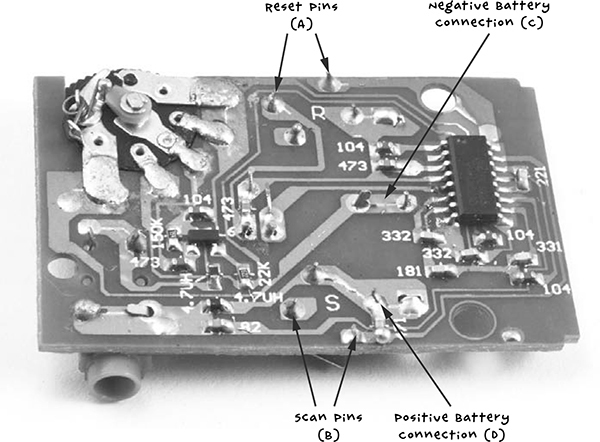
Figure 10-8: The radio PCB
The A connections are for the Reset button. If you follow the track on the PCB, you will see that one of the A pins connects to pin 16 of the SC1088 (IC pins are numbered 1 to 16 counterclockwise, with a little dot on the IC package next to pin 1).
Following the track from B, you can see that one pin connects to pin 15 of the SC1088. This is the connection that we will use to scan for the next station.
If you’re finding it hard to see where the tracks run, use your multimeter set to continuity mode to identify the pins. Press one probe to the IC pin you want to find a connection for (15 or 16) and then try the different likely connections on the switches with the other probe until the buzzer on the multimeter sounds.
Next, find the two connections needed to power the radio from the Arduino, which correspond to the battery holder connections on the PCB. The 3V batteries the radio takes have a negative central connection (C) and positive connections to the outside frame of the battery holder (D).
STEP 3: ATTACH THE HEADER STRIP
I have suggested a right-angle header strip here, because it’s easier to solder the wires to, but regular header pins work almost as well. Break off a length of 12 pins and attach them to the Arduino pins 3.3V through to A5 (Figure 10-9). One pin will sit between the two header sockets, unconnected to anything.
Figure 10-9: The Arduino header pins
STEP 4: LINK THE RADIO TO THE ARDUINO
Figure 10-10 shows the radio connected to the Arduino. Use short wires to connect the 3.3V Arduino pin to the positive battery connection, point D, that you identified earlier. Connect an Arduino GND connection (it doesn’t matter which one) to point C, the negative battery connection. Connect the positive (longer) lead of one LED to Arduino pin A0 and the negative lead of that same LED to point B. Do the same with another LED to Arduino pin A1 and point A on the radio PCB.
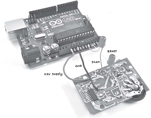
Figure 10-10: The Arduino connected to the radio
STEP 5: CONNECT EVERYTHING TOGETHER
Finally, plug the powered speakers into the radio’s audio jack. You can test this using the headphones first. The radio uses headphones or an audio lead as an antenna, so you may get better results with a longer lead of a few feet than with a very short lead.
SOFTWARE
All the source code for this book is available from http://www.nostarch.com/zombies/. See Appendix C for instructions on installing the Arduino sketch.
The Arduino sketch for this project is called Project_18_Scanner, and I’ll walk you through it now.
The sketch starts by defining several constants:
const int scanPin = A0;
const int resetPin = A1;const int pulseLength = 1000;
const int period = 5000;
const int numStations = 5;
The scanPin and resetPin constants define the two Arduino pins we’ll use, and pulseLength defines the length of the simulated button press. The scan buttons needs to be pressed for a full 1,000 milliseconds (1 second) for the radio to scan for the next station rather than simply move the frequency up a step, though this can vary depending on your radio.
The constant period tells the Arduino an amount of time, in milliseconds, to pause so you have time to register whether you are hearing a transmission or just white noise.
Next, we define a single global variable:
int count = 0;
This variable, called count, is used to keep track of the number of scans to make before resetting to the start of the FM band again.
The setup function initializes both pins as inputs (although as we shall see, this sketch is unusual in that it changes the pin mode of the pins after their first initialization).
void setup()
{
pinMode(scanPin, INPUT);
pinMode(resetPin, INPUT);
}
The loop function is where we actually scan for frequencies:
void loop()
{
delay(period);
pinMode(scanPin, OUTPUT);
digitalWrite(scanPin, HIGH);
delay(pulseLength);
pinMode(scanPin, INPUT);
count ++;
if (count == numStations)
{
count = 0;
pinMode(resetPin, OUTPUT);
digitalWrite(resetPin, HIGH);
delay(pulseLength);
pinMode(resetPin, INPUT);
}
}
First of all, the loop delays by the time specified in period. The function then sends a pulse to the scan pin to begin scanning. When the pulse has finished, the pin is set back as an input.
The count variable then increments, and when it has reached the maximum specified in numStations, a pulse is sent to the reset pin to start scanning from the beginning of the FM band again. During testing, setting numStations to 5 will allow you to check whether the project is working and finding different stations. However, after a zombie apocalypse, the airwaves should be pretty empty, so you may want to reduce this number to just 1, as any signal you happen across is bound to be transmitted by survivors (or perhaps smart zombies). If you discover any automated transmissions you want to ignore, like a distress beacon from your former boss or the murmurings of zombies inexplicably learning the rudiments of human language, change numStations to a value of one more than the number of stations you want to ignore.