I used the Arduino mounting holes and two more screws to fix the Arduino to the upright as well, but this is entirely optional. Similarly, I stuck the buzzer onto the upright with some glue (Figure 9-19).
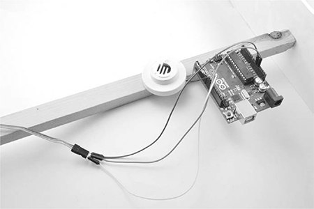
Figure 9-19: Attaching the Arduino and buzzer to the upright
STEP 7: CONNECTING THE SERVO
Servo motors have leads with three connections that terminate in a single three-hole socket: the black or brown lead is the ground connection, the red lead is the positive power supply, and the third orange or yellow lead is the control signal.
To begin wiring, plug the three male-to-male header leads into the servo’s three-hole socket. Run the orange (or yellow) control lead of the servo to pin 10 of the Arduino. Run the black (or brown) ground lead to one of the GND terminals on the Arduino. Finally, connect the red positive supply of the servo to the 5V Arduino pin. Remember: if you are using a large servo, you will probably need an external 6V battery pack, as discussed in “What You Will Need” on page 170.
SOFTWARE
All the source code for this book is available from http://www.nostarch.com/zombies/, and the Arduino sketch for this project is called Project_16_sound_ movement. Download it now and load it onto your Arduino. If you need a refresher on how, follow the directions in Appendix C.
Servos are often used with Arduinos, so there is a built-in library that makes them easy to use together. We import this library at the top of the sketch.
#include <Servo.h>
Three constants define the behavior of the servo, and tweaking the values of these constants will alter the servo’s actions:
const int minServoAngle = 10;
const int maxServoAngle = 170;
const int stepPause = 5;
Servos have a range of movement of 180 degrees. The constants minServoAngle and maxServoAngle restrict this range between 10 and 170 degrees rather than the full 0 to 180 degrees, because most servos struggle to cover the full 180 degrees.
The constant stepPause sets the delay in milliseconds between each movement of the servo. If you really want to grab a zombie’s attention, reduce this number to make the servo move more quickly.
In the next section of code, we define constants for each Arduino pin used.
const int sounderPinA = 8;
const int sounderPinB = 9;
const int servoPin = 10;
A final constant called f specifies the buzzer frequency:
const long f = 3800; // Find f using Project_16_sounder_test
Set f to your buzzer’s loudest frequency, which you should have noted in “Step 3: Test the Piezo Sounder” on page 173.
Next, to use the servo library, we define a Servo object called arm:
Servo arm;
With all the constants and global variables defined, we add a setup function to initialize the servo and define the two pins used for the buzzer:
void setup()
{
arm.attach(servoPin);
pinMode(sounderPinA, OUTPUT);
pinMode(sounderPinB, OUTPUT);
}
The loop function that follows calls two functions to wave the flag and to sound the buzzer:
void loop()
{
wave();
wave();
makeNoise();
}
The wave function is called twice to waggle the flag back and forth. In case a bit of movement isn’t enough to catch a zombie’s attention, makeNoise is also called to sound the buzzer. With any luck, the zombies will mistake the noises and movement for something with a brain and will head straight for the distraction!
At the end of the sketch, define the functions that cause the distractions:
void wave()
{
// Wave vigorously from left to right
for (int angle = minServoAngle; angle < maxServoAngle; angle++)
{
arm.write(angle);
delay(stepPause);
}
for (int angle = maxServoAngle; angle > minServoAngle; angle--)
{
arm.write(angle);
delay(stepPause);
}
}
The wave function contains two loops: one loop moves the servo from its minimum to its maximum angle at the preselected speed, and the second loop does the reverse.
Now, let’s look at makeNoise:
void makeNoise()
{
for (int i = 0; i < 5; i++)
{
beep(500);
delay(1000);
}
}
This function contains a loop that calls the beep function five times for five beeps of the buzzer. The parameter to beep is the duration of the sound in milliseconds (in this case, 500). Between each beep there is a delay of one second (1000 milliseconds).
NOTE
If using the same values all the time causes local zombies to become immune to your distractor’s effects, try tweaking the numbers you pass to beep and delay. You could even randomize the values, using Arduino’s random() function.
The beep function itself generates the AC signal on the two buzzer pins:
void beep(long duration)
{
➊ long sounderPeriodMicros = 500000l / f;
➋ long cycles = (duration * 1000) / sounderPeriodMicros / 2;
for (int i = 0; i < cycles; i++)
{
digitalWrite(sounderPinA, HIGH);
digitalWrite(sounderPinB, LOW);
delayMicroseconds(sounderPeriodMicros);
digitalWrite(sounderPinA, LOW);
digitalWrite(sounderPinB, HIGH);
delayMicroseconds(sounderPeriodMicros);
}
}
First, we calculate the period of each oscillation ➊ using the frequency f. The resulting value must be further divided by 2 ➋, because what we really want is the duration of delay between swapping the polarity of the pins, and we need two such delays for a complete oscillation.
Using that divided period, the beep function calculates the total number of cycles needed to produce a beep of the correct duration. The for loop that follows uses this information to generate the pulses that are needed.
USING THE SOUND AND MOVEMENT DISTRACTOR
Both of the projects in this chapter need to be kept dry. To weatherproof the sound and movement distractor, you might craft some kind of housing or protective roof shelter. If your build is freestanding, a large plastic bin with a lid could do the trick. I’m sure you can scavenge one from the nearest abandoned discount retail store.