Hardware store
Wood or plastic, for attachment of the upright
Hardware store
To make a flag
Household items
The power for this project is supplied through the Arduino barrel jack. The same power options as used in “Project 15: Arduino Flash Distractor” on page 158 also apply to this project.
If you just want to wave a small, lightweight flag like the one shown in Figure 9-11, a small servo motor will work just fine, but for something bigger, use a standard servo. Just be aware that if you use a bigger servo, you may find that your Arduino resets because of voltage drops caused by the load of the bigger motor. In this case, you can power the servo from a separate 6V battery pack as described at http://communityofrobots.com/tutorial/kawal/how-connect-servo-arduino/.
Also note that while this project is intended to use the buzzer removed from the smoke detector of “Project 11: Quiet Fire Alarm” on page 120, you can also just use a new buzzer.
CONSTRUCTION
Figure 9-12 shows the wiring diagram for the project.
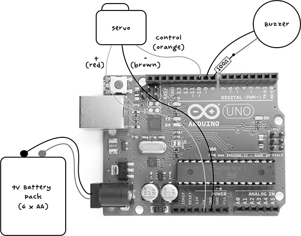
Figure 9-12: Wiring diagram for the distractor
The male-to-male jumper wires in the supply list will link the servo motor, which terminates in a three-way socket, to the Arduino. You’ll connect the resistor and one buzzer lead to a pair of header pins so that you can plug the buzzer into the Arduino, too.
STEP 1: REMOVE THE PIEZO BUZZER FROM THE SMOKE ALARM COVER
The smoke alarm’s buzzer may be integrated into the smoke alarm cover. In that case, don’t try to remove the buzzer; you can use it while it’s still attached to the cover, or you can just scavenge a different buzzer. If the buzzer looks like it will come away, then remove it as shown in Figure 9-13 to make the project a little more compact.
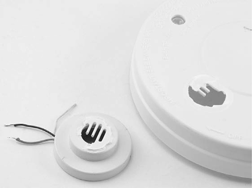
Figure 9-13: Removing the buzzer from the smoke alarm cover
STEP 2: SOLDER THE HEADER PINS, BUZZER, AND RESISTOR
Check your buzzer: you only need two buzzer leads, so if it has three, see “Project 11: Quiet Fire Alarm” on page 120 to work out which two of the three leads you need.
Once you have that cleared up, solder the 100 Ω resistor to one buzzer lead—it doesn’t matter which one. Solder the other end of the resistor to one of the header pins and the other buzzer lead to the other header pin. You may wish to strengthen these soldered connections using heatshrink (see “Using Heatshrink” on page 235) or electrical tape. These connections are shown in Figure 9-14.
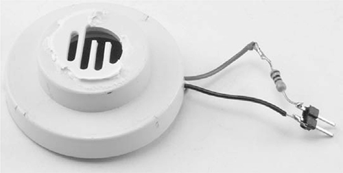
Figure 9-14: Soldering the buzzer, resistor, and header pins
STEP 3: TEST THE PIEZO SOUNDER
Before we go further, we’ll test the buzzer using the USB connection to power the Arduino. This step will help us find the optimum frequency of the buzzer to make it as loud as possible.
Plug the header pins into the Arduino pins 8 and 9. It does not matter which way around the pins are (Figure 9-15).
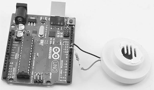
Figure 9-15: Connecting the buzzer to the Arduino
If you haven’t downloaded all of this book’s programs yet, go to https://www.nostarch.com/zombies/ and download the Project_16_Sounder_Test Arduino sketch. Load this sketch onto your Arduino and then open the serial monitor (Figure 9-16). This is not the final sketch for the project; it’s just a test sketch that will let us find the best frequency value to use in the main sketch.

Figure 9-16: Setting the frequency using the serial monitor
In the input field, enter 4000 and click Send—this number is the frequency of the sound your buzzer will emit. You should hear a very loud sound at that frequency for a second. Try entering different frequency values to find the one that gives the highest volume; it will probably be around 4000.
To reduce the strain on your ears, you can turn the buzzer over or cover the hole where the sound emerges to muffle the volume. When you have found the optimum frequency, make a note of the value.
NOTE
This is definitely something to do when there are no zombies around.
PIEZO BUZZERS
Piezo buzzers (also called sounders) contain crystals that change shape when a current is passed through them. The current changes hundreds of times per second, and as the crystals change shape, sound waves are produced. Although you can drive a piezo buzzer by connecting one lead to GND and supplying a signal to the other lead, you get a higher volume by using two Arduino outputs to completely reverse the polarity of the buzzer with each cycle. Figure 9-17 shows how this works.
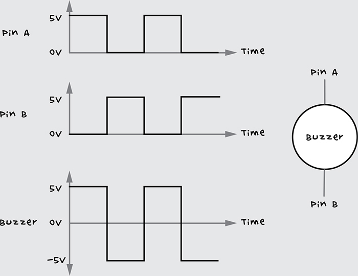
Figure 9-17: Generating an alternating voltage on the piezo buzzer with an Arduino. Pins A and B are outputs on the Arduino.
When one Arduino output is high, the other is low and vice versa. This complete reversal of the polarity across the piezo buzzer effectively allows a 10V peak swing of voltage across the buzzer rather than the 5V obtainable from just switching one pin.
Your distractor will not be as loud as the original smoke detector, which typically uses the same trick but with 9V rather than 5V. However, it should be pretty loud.
STEP 4: MAKE A FLAG
My distractor waves a flag, but yours doesn’t have to. Once you have the servo moving, you can attach pretty much anything that will attract the attention of zombies. Try a scrap of rotting meat to get a good zombie-attracting scent going, or if your servo is powerful enough, you might salvage a severed hand for a more realistic human distraction.
Assuming that you just want to wave a flag, the simple arrangement from Figure 9-11 uses a piece of paper folded and glued to a wooden kebab skewer.
STEP 5: ATTACH THE FLAG TO THE SERVO MOTOR
Servo motors generally come with a range of arms and a retaining screw to fix the arm in place on the motor. In this project, I chose the wheel fixture and glued the skewer to it with strong epoxy glue (Figure 9-18).
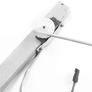
Figure 9-18: Attaching the flag to the servo
Don’t fit the servo motor’s retaining screw just yet, as you will need to adjust the position of the servo arm to accommodate the range of movement (around 160 degrees) once the whole project is up and running.
STEP 6: ATTACH THE SERVO MOTOR TO A BASE
For an upright to attach to the servo motor, I’ve used a length of wood. To attach the servo, cut a little notch in the wood to fit the servo using a wood saw or small electric hobby cutter. Then use the servo mounting holes and some small screws to fix the servo in place.
As an exercise in ingenuity, I’ll leave it up to you to find the best way to attach your servo to your upright. Here, I used a small piece of scrap aluminum to hold the servo in the notch. Epoxy glue would also work.
Now, attach the upright to a base. I drilled a hole in the underside of a flat piece of acrylic and attached the wooden upright with a screw. You may prefer to fix the upright directly to some existing structure, rather than using a freestanding arrangement. (Again, I’ll leave the details to your discretion.)