$ Connected /dev/rfcomm0 to 00:11:04:08:04:76 on channel 1
Press CTRL-C for hangup
$
You’ll need to run this command before you run the program each time your Raspberry Pi reboots. The & on the end of the command runs it in the background so that you can use the terminal window to run the program itself. Hit ENTER to get the $ command prompt back.
If your Bluetooth interface name did not have a 0 after hci when you ran the hciconfig command earlier, change the first 0 after connect to match the number on the end of hci. Remember when I asked you to make a note of this number?
Finally, move to the project directory and run the program:
$ cd ~/zombies/control_center_bt/
$ python control.py
If you look at the control.py files from this project and Project 13, you can see that the only difference is the port. In this version of control.py, we set the port to /dev/rfcomm0 rather than /dev/ttyACM0 so that it uses the Bluetooth connection rather than the USB connection.
USING THE BLUETOOTH-ENABLED COMMAND CENTER
The project works in exactly the same way as the USB version in Project 13, with the window displaying the same information, only now it’s a little more portable as long as your webcam is wireless. If zombies get into your compound, just grab the Raspberry Pi, monitor, and power source and barricade yourself inside a closet until they lose interest.
In the next chapter, we’ll work on ways to distract zombies in a pinch, because the undead are usually much easier to run from than they are to actually kill.
9
ZOMBIE DISTRACTORS

It doesn’t take much to fool a zombie so you can make a quick escape (see Figure 9-1). They are rather lacking in brains, after all. The projects in this chapter are designed to draw zombies’ attention away from you using flashes of light, loud sounds, and decoy movements. Imagine you have a herd of zombies lurching around the garage door but you need to get to your last remaining car battery. These distractors will allow you to draw the zombies away from the door or even lure them into a fatal zombie trap, perhaps involving fire and a big hole in the ground.
The first project uses flash units from disposable cameras to produce a disorienting series of flashes to confuse the zombies. The second project uses sound and movement to attract the zombies’ attention. Build these projects and affix them to key locations in your base so you can direct zombies away from you.
Figure 9-1: Smile please!
PROJECT 15: ARDUINO FLASH DISTRACTOR
This flash distractor combines an Arduino and old disposable cameras to produce a timed series of flashes that will confound your brain-hungry foes. Proprietors of old-fashioned photo developer stores are often happy for you to take armfuls of used disposable film cameras off their hands. This is especially true if the proprietors are the animated deceased. They might appear to grumble at you, but I assure you, whatever groaning noises they make are entirely coincidental.
Figure 9-2 shows the completed zombie flash distractor with three salvaged single-use flash cameras, modified to allow the flashes to be triggered by an Arduino. The three cameras are taped together as a block with all the flashes pointing outward.
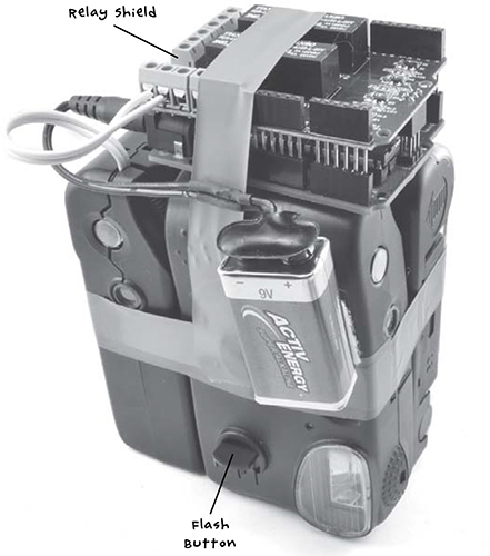
Figure 9-2: The completed zombie flash distractor
The three flash modules are arranged so that each one points at a right angle to every other, giving 270 degrees of coverage. You will need a separate Arduino for this project as you will not want to position this right next to your control center.
WARNING
If you have a pacemaker or heart problems, or if flashing lights give you seizures, do not build this project.
WARNING: HIGH VOLTAGES AND BRIGHT FLASHES
Flashguns in disposable cameras operate at up to 400V DC. If you want to avoid an unpleasant shock, exercise extreme caution when taking the cameras apart and handling the flash modules. Many parts of the module will be at high voltage and can remain so for hours or even days. Before using the modules, make sure to follow the instructions in “Step 3: Make the Camera Safe!” on page 163 to safely discharge the capacitor.
WHAT YOU WILL NEED
To make this project, you will need the following parts:
ITEMS
NOTES
SOURCE
Arduino Uno R3
Adafruit, Fry’s (7224833), Sparkfun
4-channel relay shield
eBay, http://www.sainsmart.com/
3 used disposable flash cameras
Photo store
PP3 type 9V battery, or larger 9V or 12V battery pack
Hardware store
DC power jack to 9V battery clip adapter
Adafruit (80), eBay
Three 6-inch (15 cm) lengths of bell wire or other double-core wire
Hardware store, scavenge
Auto parts store
For discharging the camera’s flash capacitor
Mouser (293-100-RC)
There are few uses for spent disposable cameras and a store’s only alternative is to pay for someone to take them away, so if you ask store owners nicely, they may give you a stack for free.
Along with a perfectly fine flash module, each camera will generally have an almost unused AA or AAA battery. Try to get a set of cameras that are similar to each other, ideally cameras of the same make. (In the bag of cameras I took away, the most common brand was Fuji, so I based the project on that design. However, the instructions should be sufficiently general to work with any disposable camera.) Also, find cameras that have a switch that turns the flash on for multiple photos, not the sort that make you press the flash button between each shot. For example, look at the camera at the front of Figure 9-2. It has a kind of lever that keeps the flash turned on (bottom center of the figure).
The relay shield was bought on eBay, and when you attach it to the Arduino, it connects a relay to Arduino pins 4, 5, 6, and 7. If you end up with a slightly different relay shield, just check which digital Arduino pins it uses and make the necessary changes in the Arduino sketch (see “Software” on page 166).
The 100 Ω resistor is used to discharge the large, high-voltage capacitor used in the flash module to avoid the risk of electric shocks. It plays no other part in the build.