CONSTRUCTION
To enable Bluetooth connectivity for your Raspberry Pi, you only need to attach a USB dongle to your system.
The Arduino requires the aforementioned Bluetooth module and a pair of resistors to divide the 5V signal level of the Arduino to the 3V level expected by the Bluetooth module. Mount the module and resistors to the side of the screwshield’s prototyping area not already being used by the fire alarm interface from Project 11.
Figure 8-7 shows the wiring layout for the project. To avoid confusion, Figure 8-7 shows the Bluetooth module attached to a screwshield without any other projects built on it.
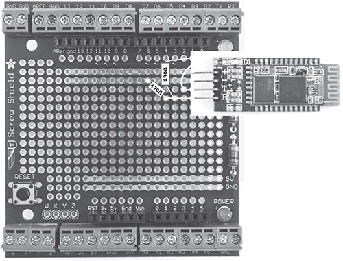
Figure 8-7: Wiring layout for adding Bluetooth to an Arduino
The Bluetooth module needs to lie flat to keep it out of the way of the LCD shield. For this, you need to solder a row of four 0.1-inch header pins and then solder the Bluetooth module perpendicular to the pins, lying flat over the screwshield. If you prefer, you may also use female-to-female jumper wires to connect the Bluetooth module to the header pins.
STEP 1: SOLDER THE HEADER PINS
Solder the strip of header pins into place. You can see in Figure 8-8 that the +5V and GND pin connections neatly line up with the two power rows at the top of the screwshield.
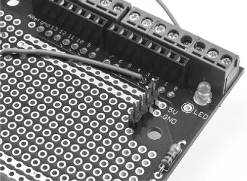
Figure 8-8: The header pins soldered in place
Note that the wire shown leading to pin 3 of the Arduino is part of the fire alarm from Project 11, not this project.
STEP 2: SOLDERING THE RESISTORS AND LINKING WIRE
Solder the resistors and linking wire to the screwshield in the positions shown in Figure 8-9: the 470 Ω resistor goes from GND at Arduino column 7 to the bottom header at column 4; the 270 Ω resistor goes from the bottom pin of the header at row 3 to Arduino pin 1. The connecting wire runs from Arduino pin 0 to the third header pin down.
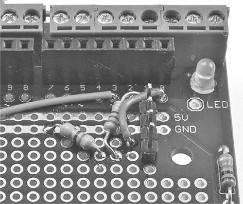
Figure 8-9: Soldering the resistors and connecting wire
When you’ve soldered the resistors and connecting wire in place, flip the screwshield over to solder the underside of the board.
Figure 8-10 shows a close-up of the underside of the screwshield. To make it easier to identify what is connected to what, the resistors and linking wire are shown as if they were visible through the board.
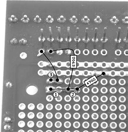
Figure 8-10: Connecting the underside of the screwshield
First, bend the bottom lead of the 270 Ω resistor over toward the bottom pin header ➊. Solder this to the bottom pin header’s pad and snip off the remaining lead. Bend the remaining lead from the bottom end of the 470 Ω resistor to meet the pad one position to its left ➋. Solder the lead to that pad and snip off the excess lead. You have now made a continuous connection from the bottom of the header pins to the bottoms of the 270 Ω resistor and the 470 Ω resistor.
The final connection on the underside ➌ uses the spare wire from soldering the lead from the jumper wire to the header pin to its immediate left.
STEP 3: SOLDERING THE BLUETOOTH MODULE
The final step is to solder the Bluetooth module to the header pins. Solder one pad on the module to one of the header pins, and while keeping the solder molten, position the Bluetooth module so that it is resting against the 1 kΩ resistor that came attached to the screwshield. Then attach the first prong of the module to the first pin. You can see this resistor on the bottom right of Figure 8-9. Once the first prong is soldered, all the other prongs should be lined up and easy to solder. If you prefer, you could use female-to-female jumper wires to link the screwshield to the Bluetooth module. Figure 8-11 shows the Bluetooth module in position.
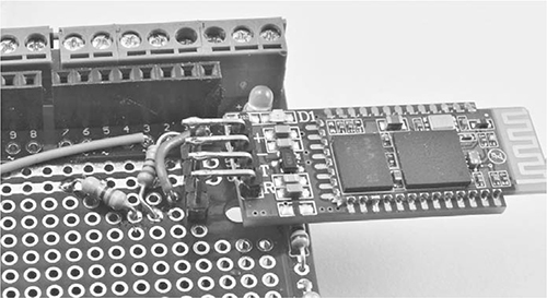
Figure 8-11: The Bluetooth module soldered in position
SOFTWARE
Since your sensors aren’t changing, you’ll use the same Arduino software as in “Arduino Software” on page 143. The Bluetooth module replaces the USB interface.
Note that this hardware communicates with the Bluetooth module using the serial port, which on an Arduino Uno is shared with the USB interface. This means that you need to unplug the shield (or just the Bluetooth module if you used jumper wires) before you program the Arduino.
The Raspberry Pi software, however, does need a couple of minor changes, and getting the Raspberry Pi to use Bluetooth does require you to install a whole load of software. Remember: You’ll need to install this software before the Internet fails!
Plug the Bluetooth USB adapter into a free USB slot on your Raspberry Pi and then run the following commands in an LXTerminal window:
$ sudo apt-get update
$ sudo apt-get install bluetooth
$ sudo apt-get install bluez-utils
$ sudo apt-get install blueman
Installing the software will take a considerable amount of time, so you might want to practice your martial arts skills on any willing humans or unwilling zombies available.
When the software is installed and you’ve worked up a good sweat, reboot the Raspberry Pi with this command:
$ sudo reboot
Once the Raspberry Pi has rebooted, open a terminal and run the following command to ascertain the ID of the BT interface:
$ hciconfig
➊ hci0: Type: BR/EDR Bus: USB
BD Address: 00:15:83:0C:BF:EB ACL MTU: 339:8 SCO MTU: 128:2
UP RUNNING PSCAN
RX bytes:419213 acl:19939 sco:0 events:7407 errors:0
TX bytes:95875 acl:7321 sco:0 commands:57 errors:0
The information we want here is the name of the interface, which in this case is hci0 at ➊. When you run this, if the number after hci above is not 0, then make a note of the number; you will need it later.
Every Bluetooth device has a unique ID called a MAC address. We need to find the MAC address for our new Arduino Bluetooth module to pair it with the Raspberry Pi. When you power up the Arduino, you should see an LED blinking on the Bluetooth module. The LED is blinking because it has not yet been paired up with the Raspberry Pi; once it has been paired, the LED will go on and stay on. Run the following command to find the ID of the Bluetooth module:
$ hcitool scan
The output from the hcitool command should look like this:
Scanning ...
00:11:04:08:04:76 linvor
The ID is the six-part number. Copy this into the copy-and-paste buffer (Copy and Paste are on the right-click menu). Then enter the following command to link the Raspberry Pi and the Bluetooth module (remember to change the Bluetooth ID to match your Bluetooth module’s ID):
$ sudo hcitool cc 00:11:04:08:04:76
If you have not already done so, follow the instructions in “Raspberry Pi Software” on page 145 for downloading the Raspberry Pi software. You will find the Bluetooth version of control.py in the folder Raspberry Pi/control_center_bt.
When you have the program, run the following sudo command, again replacing the Bluetooth ID with your own:
$ sudo rfcomm connect 0 00:11:04:08:04:76 1 &
[1] 2625