The temperature in degrees Celsius is then calculated using the formula described in “TMP36 Temperature Sensor” on page 133, as the voltage multiplied by 100 with 50 subtracted from the result. The temperature in degrees Fahrenheit is also calculated.
Finally, one of these two values has to be returned. In this version of readTemp, the line to return tempF is commented out, so the temperature in Celsius will be returned. If you want to flip this, then comment out the line return tempC and un-comment return tempF so that the last three lines of the function look like this:
// return tempC;
return tempF;
}
To test the sensor, try changing the value of the maxTemp constant to just above the room’s temperature, load the updated sketch onto the Arduino, and then squeeze the temperature sensor between your fingers to warm it up. Watch the LCD, and the readout should change.
USING THE TEMPERATURE ALARM
There’s a limit to how much distance you can put between your temperature sensor and your Arduino. You could make the lead you attach to the TMP36 as long as 20 feet (7 m), but the sensor will become less and less accurate as the lead gets longer due to electrical noise on the line and the resistance of the wire.
Leave the sensor near the item you want to stay at a certain temperature and watch the LCD. If that wine cellar just won’t stay cool enough, try setting up the sensor in different rooms in your base until you find one with the right climate. If there isn’t a good room for the wine, just put the sensor back on your generator, invite the other survivors in your area over for a drink, and have an antizombie strategy meeting.
Now that you have a bunch of sensors to warn you of dangers in your base, in the next chapter, you’ll combine the Arduino projects with a Raspberry Pi to make a control center.
8
BUILDING A CONTROL CENTER FOR YOUR BASE

In this chapter, you’ll learn how to make an integrated control center using a Raspberry Pi computer interfaced with earlier projects from this book. The control center will allow you to monitor all of your alarm and surveillance devices on one screen so you’ll know instantly if a zombie has breached your compound (Figure 8-1). As an extra feature, you’ll learn how to add wireless connectivity to your control center.

Figure 8-1: A quiet night at the security desk
PROJECT 13: A RASPBERRY PI CONTROL CENTER
In this project, you’ll connect the Raspberry Pi system of Chapter 5 with the following Arduino monitoring devices developed earlier in the book:
• “Project 4: Battery Monitor” on page 53
• “Project 6: PIR Zombie Detector” on page 72
• “Project 10: Door Sensor” on page 112
• “Project 11: Quiet Fire Alarm” on page 120
• “Project 12: Temperature Alarm” on page 131
We’ll link the two boards with USB cables, which we can later replace in Project 14 with a wireless Bluetooth link. The Arduino will still be able to work without the Raspberry Pi after this wireless modification, but linking it to the Raspberry Pi will allow you to show the status of your sensors and alarms in a window on the Raspberry Pi. Figure 8-2 shows the setup; you can see the sensor status window in the center of the screen.
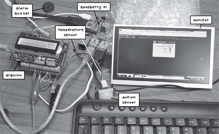
Figure 8-2: Raspberry Pi and Arduino working together
WHAT YOU WILL NEED
This project brings together the Raspberry Pi system of Chapter 5 and most of the Arduino projects described in the book thus far. As such, all you will need is the following:
CONSTRUCTION
Assuming that you have been slowly adding projects to your Arduino, the Arduino now has five projects attached to it. If you’re really prepared, you probably built these ages ago and have them stashed in your go bag, ready for the apocalypse. Either way, you should at least have the sensors you are interested in using.
If your Arduino projects and Raspberry Pi are already set up, you won’t need to do much construction to link them. You connect an Arduino project to the Raspberry Pi by plugging one end of the USB lead into the Pi and the other end into the Arduino. If your Raspberry Pi does not have any free USB ports, then you will need to add a USB hub to provide more ports.
Now that you have linked your Arduino and your Raspberry Pi, you’ll need to program them. It’s best to program the Arduino from your regular computer before swapping the USB cable over to the Raspberry Pi, as programming the Arduino from the Raspberry Pi’s small screen can be frustrating.
Figure 8-3 shows the arrangement of the various system components.
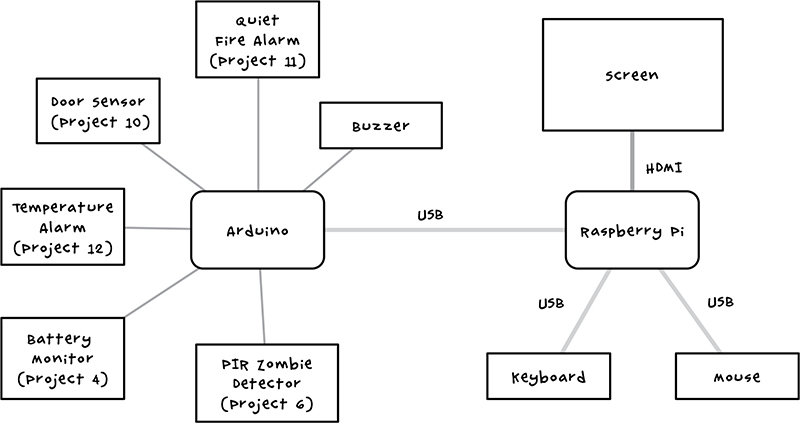
Figure 8-3: A schematic of the control center
This arrangement plays to the strengths of both the Arduino and Raspberry Pi. The Raspberry Pi cannot directly use many of the sensors that are connected to the Arduino, while the Arduino can. At the same time, the Arduino does not have a screen, while the Raspberry Pi does.
SOFTWARE
There are two parts to the software for this project: a modified version of the All_Sensors Arduino sketch and a Python program run on the Raspberry Pi to allow it to communicate with the Arduino.
Before the apocalypse, make sure you’ve downloaded the source code for this book; go to http://www.nostarch.com/zombies/ to get started.
ARDUINO SOFTWARE
The Arduino sketch you will use for this project, Project_13_Control_Center_ USB, is based on the All_Sensors sketch that runs all of the other Arduino projects in this book. Project_13_Control_Center_USB just adds code to allow your Arduino to communicate with other devices over a serial connection (in this case, USB).
NOTE
For instructions on loading sketches onto your Arduino, see Appendix C.
It’s best to test each part of this fairly complex system in isolation on your regular desktop or laptop computer before connecting it to the Raspberry Pi. You can power the Arduino from the USB connection to your laptop while testing, so you don’t need to use your postapocalyptic car battery power supply for preapocalyptic testing.
To begin testing, load the Project_13_Control_Center_USB sketch onto the Arduino and click the magnifying glass in the Arduino IDE to open the serial monitor (Figure 8-4).
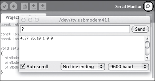
Figure 8-4: The serial monitor
Make sure that “9600 baud” is selected in the drop-down list at the bottom right of the serial monitor. This is the baud rate, the speed at which data is sent (measured in bits per second), and it must match the speed set in the sketch.
In the text entry area at the top of the serial monitor, enter the ? command and click Send. The Arduino should display a line of numbers like the 4.27 26.10 1 0 0 shown in Figure 8-4 (your numbers will not match these, exactly). These numbers are the battery voltage, temperature, door status, PIR status, and smoke alarm status, respectively. For the three status values, 0 means everything is okay and 1 indicates an alarm. These are the values that will later be displayed on the control center. By simulating how the Raspberry Pi will fetch the values, you are testing that the Arduino part of the project is working.