Double core and long enough to reach from the smoke detector to the Arduino
Scavenged speaker or bell cable is good for this.
1N4001 diode
Adafruit (755)
1 kΩ resistor
Mouser (293-1k-RC)
Blue or white LED
Adafruit (301)
100 µF capacitor
Adafruit (753)
2 inches (5 cm) long
Abandoned electronics, Adafruit (1311)
Be sure to use the LED colors I recommend, as I don’t suggest blue or white LEDs just because they look cool. For this project’s circuit to work, the LED needs to have a forward voltage of more than about 2V. Red and green LEDs often have a forward voltage of about 1.7V, but blue and white LEDs have a much higher forward voltage of around 3V, which is perfect.
CONSTRUCTION
To adapt the smoke detector to communicate silently with the Arduino, you’ll disconnect the detector’s buzzer from its circuit board and then change the signal that would go to the buzzer into a signal the Arduino can use. You’ll condition the buzzer signal by sending it through the circuit (Figure 7-3).
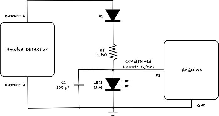
Figure 7-3: Schematic for the fire alarm
A typical smoke alarm is really loud because its buzzer is driven with the highest possible voltage the circuit can wring out of a little 9V battery. This means that for most alarms, the signal on the buzzer looks something like the chart on the left of Figure 7-4.
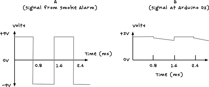
Figure 7-4: Taming the buzzer signal for Arduino is much easier than taming a zombie!
The buzzer is driven by an alternating current (AC) square wave, with a voltage that swings from +9V to –9V at roughly 600 times per second. This causes a piezo element to alternately expand and contract, generating the buzzing sound. But this voltage swing is too wild for the Arduino, which can be damaged by inputs greater than 5V or less than 0V.
The circuit to convert the buzzer signal begins with the diode D1, which completely prevents the negative voltages from reaching the rest of the circuit (diodes only allow current to flow in one direction). The resistor limits the current flowing to the LED, which limits the voltage across the LED to about 3V. The capacitor gets rid of any voltage spikes and smoothes out the signal to something like the chart on the right in Figure 7-4.
STEP 1: DISCONNECT THE BUZZER
First, disassemble the smoke detector. When you remove the lid, you should see a PCB and some wires (Figure 7-5).
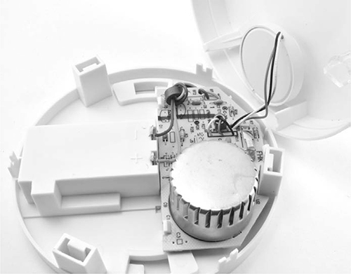
Figure 7-5: Inside the smoke detector
In this smoke detector, the three leads going from the circuit board to the lid are the buzzer leads. Chop off the leads to the buzzer now, but don’t cut too close to the buzzer itself. Resources are scarce during an apocalypse, and you might want to repurpose that buzzer later.
DANGER: RADIATION!
As you start this project, keep two warnings in mind. First, if you take apart your smoke detector before the zombie outbreak, do not use it as a smoke detector again. Smoke detectors save thousands of lives a year, so don’t rely on one you’ve messed with; just buy a new one.
Second, although removing the smoke detector’s plastic case is safe, if your smoke detector has a round metal box inside (see Figure 7-5), do not open that box, as it contains a radiation source that ionizes air in a small chamber. Smoke particles will absorb the ions, and the resulting reduction in current through the ionized air triggers the alarm. This type of smoke detector is gradually being replaced by designs that detect smoke optically instead, so hopefully, yours won’t have that box at all.
NOTE
You can use the buzzer from your smoke detector to build “Project 16: Arduino Movement and Sound Distractor” on page 169. If you’ve ever been close to one of these smoke alarms when they sound, you’ll know just how distracting they are!
Your buzzer may have two leads or three leads. If it has three, follow Step 2 to determine which lead is which. If it has just two, these are the leads that you will connect to, and you can skip Step 2.
STEP 2: IDENTIFY THE LEADS
If your buzzer has three connections, then your smoke alarm uses a type of piezo buzzer called a self-drive piezo. The third connection is called the feedback connection and is used to make the piezo sound as loud as possible.
For this project, you just want the two drive connections on the smoke detector. Sometimes the wires are color coded; if so, the drive connections will probably be red and black, and the feedback connection might be white (see Figure 7-6) or some other color. But if you have a multimeter, then you can just check which wires are the drive wires and avoid guesswork. Figure 7-6 shows this process in action.

Figure 7-6: Identifying the smoke alarm buzzer wires
Strip the ends of all three wires and set your multimeter to its 200V AC range if it’s available on your meter, or at least the 10V AC range. (Yes, I mean AC, not the usual DC.) Connect the multimeter leads to any two of the three wires and measure the voltage as you hold down the contacts of the smoke alarm’s “test” switch. If the meter indicates about 9V, or anything above 4V or 5V, then these are the wires you are looking for; otherwise, try different pairs until you find the correct wires. Note that the project relies on the battery or batteries still being present in the smoke alarm.
STEP 3: SOLDER COMPONENTS TO THE SCREWSHIELD
This circuit has too many components to attach all of them to the screw terminals, so use the prototyping area on the screwshield to solder the components into place. Figure 7-7 shows the wiring diagram for the screwshield; the letters marked will be used later to describe just how to solder this together.
NOTE
For the sake of clarity, Figure 7-7 doesn’t include components from earlier Arduino-based projects that might be hanging off the screwshield.
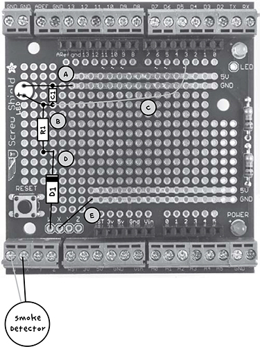
Figure 7-7: Wiring diagram for the screwshield
Holding your screwshield so that it looks like Figure 7-7, push the component legs through from the top of the board. Note that the diode (labeled D1) and LED are polarized, meaning they only work when oriented a certain way. Point the diode’s stripe toward the top of the board. Then place the LED’s longer lead (the positive lead) toward the bottom of the board (Figure 7-7).
When you’ve pushed all the component leads through, flip the board over and solder the leads where they emerge from the hole. (If you are new to soldering, take a look at Appendix B, especially “Soldering a PCB” on page 234.) It may help to bend the leads slightly so that the components don’t fall out when the board is upside down. When all the components are soldered, the underside of the board should look like Figure 7-8.