STEP 3: FITTING THE DOOR LATCH
The electric door latch used in this project is designed to fit into a wooden door frame. If you have a different type of door, search for other 12V door lock mechanisms. Just remember: 12V latches that rely on an electromagnet to keep hold of a metal plate won’t keep your base safe. That kind of lock needs to be powered continuously to stay locked, meaning if the battery is empty, your door unlocks and lets all the zombies inside.
To fit the electric door latch, replace the old door latch plate with the electric latch plate. The electric version requires a considerably bigger hole in the door frame to contain the body of the latch, so drill and chisel this hole out; one possible result is shown in Figure 6-8.
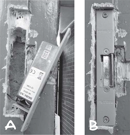
Figure 6-8: The latch hole (A) and the fitted door latch (B)
Figure 6-8a shows the latch hole, with a hole drilled at the side to allow the two wires from the lock to be led through to the inside of the door. Figure 6-8b shows the latch fitted back into place. The right edge of the latch releases when power is applied to the latch.
STEP 4: WIRING
Push the ends of the battery lead you made in Step 2 through one of the holes you added to the side of your enclosure in Step 1. Next, wire the positive battery connection to middle position of the three-way terminal block and wire the negative connection to the bottom position.
Unless you’re mounting your button right by the door, extend the two wires from the door latch to a reasonable length by joining the short wires of the latch to the longer wire with a two-way terminal block. Then, thread the door latch’s long wire through the hole in the back of the switch box and connect it to the top and bottom positions of the screw terminal, as shown in Figure 6-5. When the wiring inside the box is complete, it should look something like Figure 6-9.
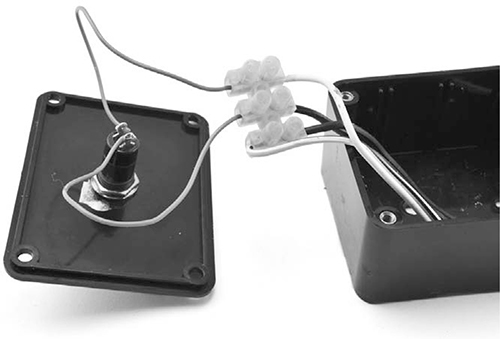
Figure 6-9: Wiring up the switch box
The light-colored wires on the right are for the door latch, and the dark wires are the battery leads. Before you close it all up, just check that pressing the button releases the lock and tidy up the wiring in the box. Finally, affix the door lock’s lead to the wall so that it isn’t a trip hazard, and you’re done!
Of course, your safe haven would be even more accessible if you could unlock the door from a distance, so let’s add a remote control.
GOING WIRELESS TO OPEN DOORS AHEAD OF TIME
You could stop after installing a button, but one day, that button won’t be fast enough. When you’re fresh off a scavenging trip, loaded down with precious supplies and running for your life because a mob of zombies decided to follow you home, you’ll wish you could open the door before you reach it. Plan ahead and make the door remote controlled.
To make control of the lock wireless, you can use an RF remote control relay. The relay will be wired in parallel with the push button so if the button is pressed or the remote is activated, the door will unlock.
Figure 6-10 shows the wiring diagram for the project, this time including the wireless remote.
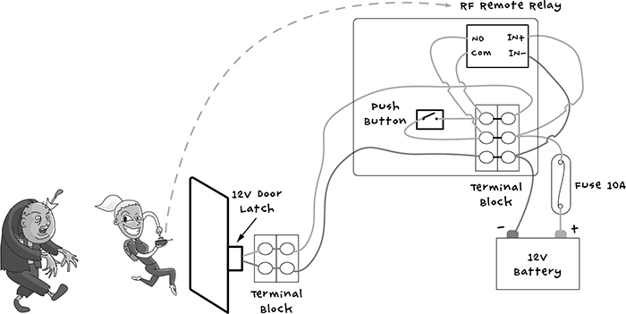
Figure 6-10: Schematic for the electrical door latch with a wireless remote
The push button is connected to the same screw terminals wired to the NO (normally open) and COM (common) connections on the relay. The RF relay module requires a 12V power supply taken from the terminal block’s connections to the battery negative and the fuse. Figure 6-11 shows how the relay fits into the same box used for the first part of the project.
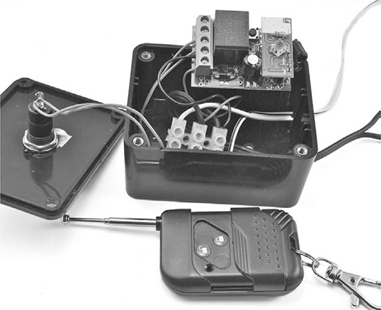
Figure 6-11: Wiring the wireless relay to the electrical door latch
Wire in the relay according to the diagram in Figure 6-10, and then you’ll just need to remember to take your wireless remote with you when you head out to forage or thin out the zombie population. And always bring along a spare remote, or at least a spare battery! As a final backup, you should always keep the real key with you too.
PROJECT 10: DOOR SENSOR
While the first project in this chapter helps you and your loved ones get to safety, the second project alerts you to uninvited guests. Whether a stray zombie or another survivor manages to open the door to your stronghold, with this door sensor, you’ll know about perimeter breaches in time to hide.
This project uses a reed switch (if you’ve never used one, check out “Reed Switches” on page 113 for a detailed description) to detect when a door has been opened, triggering a message on your Arduino. This project uses the same Arduino that monitors your battery and watches for zombies using the PIR detector.
REED SWITCHES
The sensor used in this project is called a reed switch. This switch is made from a pair of thin steel contacts enclosed within a sealed glass envelope. This envelope is often further protected by a plastic box with screw holes for fastening it to a door or window frame.
As shown in Figure 6-12, with no magnet present, the contacts are slightly apart, but when a magnet is brought close, the two contacts are pulled together, and an electrical connection is made.

Figure 6-12: A reed switch
Because reed switches are sealed, they are very reliable. For this reason, they’re often used in security applications where the magnet is attached to, say, the door itself and the reed switch to the door frame. When the door is opened, the magnet moves out of range of the reed relay, and the circuit is broken.
WHAT YOU WILL NEED
To make this project, you’re going to need the Arduino and screwshield that you used in “Project 4: Battery Monitor” on page 53, plus a few other parts.
ITEMS
NOTES
SOURCE
After the apocalypse, you can scavenge these from any house that has an intruder alarm.
Adafruit (375), Fry’s (1908354), security store
Speaker cable works well.
Hardware store, scavenge
2-way 2A terminal block
Home Depot, Lowe’s, Menards
Arduino Uno R3
Adafruit, Fry’s (7224833), SparkFun
Screwshield
Adafruit (196)
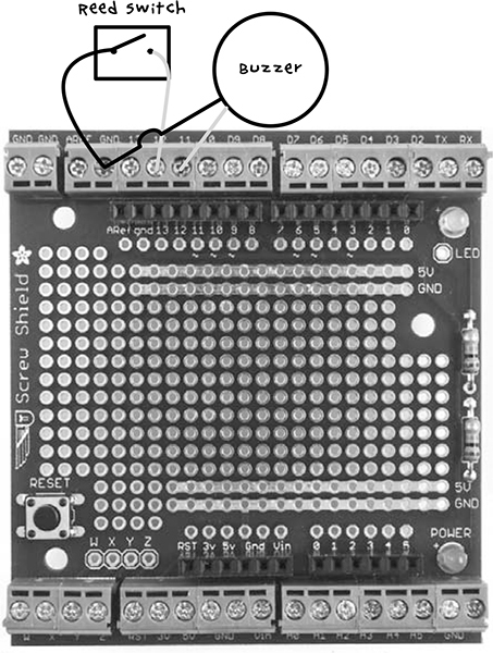
The reed switch will be further from the Arduino than the short leads that it comes with would allow, so you’ll need to extend those leads. Using the double-core wire, either connect the wires together with solder (see “Joining Wires with Solder” on page 231) or connect them to a two-way terminal block.
CONSTRUCTION
Figure 6-13 shows the wiring diagram for connecting the reed switch to the screwshield. You will need the buzzer from “Project 4: Battery Monitor” on page 53, but the resistors are only needed if you also want to monitor the battery voltage.