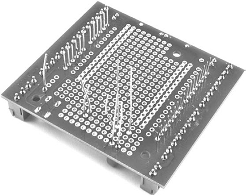
Figure 7-8: Fixing the components in place
Now that the components are fixed, bend the leads and arrange them to make the connections, using Figure 7-9 and the steps below as a guide. (The connections described below are indicated in Figures 7-7, 7-9, and 7-10 with letters.)
1. Bend the top (negative) lead of the LED over so that it lies next to the top lead of C1 and the GND power line on the screwshield (A). Solder the LED lead where it crosses C1 and then where it meets the GND line. Cut off the excess LED lead and the remainder of the top lead of C2.
2. Bend the other LED lead over to run next to the top lead of R1 and the bottom lead of C1 (B). Solder the bottom LED lead at the junctions where it crosses R1 and C1 and cut off the remainders of both the C1 lead and the R1 lead you just soldered to. If there is any remaining LED lead after connecting to R1 and C1, cut that off too.
3. Cut a length of solid-core wire that is long enough to reach all the way from the end of the positive LED that you soldered in Step 2 as far as D3 on the top Arduino connector (C). Strip the ends of the wire (see “Stripping Wires” on page 227). Flip over to the top side of the board and push one stripped end of the wire into a hole next to where the positive LED lead connects to C1 and solder the wire to that junction. Solder the other end of the wire to the solder pad next to Arduino pin 3. Push the stripped end through the hole from the top and solder on the underside.
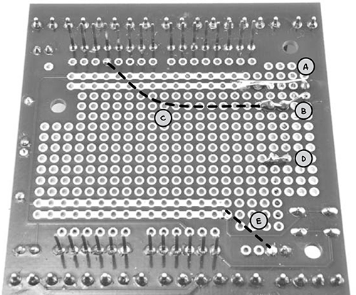
Figure 7-9: The underside of the screwshield, after soldering. The dashed lines indicate wires running on the top of the shield.
4. Bend the bottom lead of R1 over so that it crosses the top lead of D1 (D). Solder these leads together and cut off the excess wire.
5. Use another short length of solid-core wire (or if they are long enough, one of the leads you trimmed off R1) to connect the solder pad labeled X to the bottom GND power line on the screwshield (E).
When this is done, the underside of the board should look like Figure 7-9. The dotted lines represent the wires on the other side of the board.
Next, flip the board over and add a wire to link pin D3 (just marked 3 on the screwshield) of the Arduino to the junction of the capacitor, diode, and resistor. Solder that wire in place. When this is done, the top of the screwshield should look like Figure 7-10.
Now that the board is complete, reassemble the electronics by fitting the display shield back on top of the screw shield and the screw shield onto the Arduino.

Figure 7-10: The finished screwshield
STEP 4: CONNECT THE SMOKE DETECTOR TO THE ARDUINO
Finally, strip the buzzer wires if you haven’t done so already, and solder longer leads to them. To make the soldered connections stronger, you could use heatshrink as described in “Using Heatshrink” on page 235. Connect the smoke detector to pins W and X on the screwshield. The wire connecting the smoke detector to the Arduino can be any double-core cable, such as bell wire, but if you plan to use this alarm in your base, just use wires long enough to reach the mounting position. I found that the project worked just fine with 30 feet (10 m) of telephone extension cable.
SOFTWARE
If you want to make this project without any of the other Arduino-based projects in this book, then load the sketch Project_11_Smoke_Alarm from this book’s source files onto the Arduino now. If on the other hand, you’ve built one or more of this book’s earlier Arduino projects, then use the sketch All_Sensors and change the constants at the top to select the projects that you’ve made. See the comments section in that sketch for instructions on the correct changes to make.
NOTE
You’ll find a link to the source code for this book at http://nostarch.com/zombies/. See Appendix C in this book for instructions on loading the programs.
This code builds on the code from Project 4, so for more information on how the program as a whole works, please refer to “Software” on page 57. Here I will just describe the code specific to the fire alarm.
First, we define a new constant for pin D3 on the Arduino:
const int smokePin = 3;
This pin will act as an input for the signal from the smoke detector. After adding the smokePin constant, we add a new line of code to the setup function to initialize this pin as an input:
pinMode(smokePin, INPUT);
Next, we add a call to a new function called checkSmoke to the loop function. The checkSmoke function is defined as follows:
void checkSmoke()
{
if (digitalRead(smokePin))
{
alarm("FIRE!!");
}
}
The checkSmoke function contains the rest of the code for checking for a signal from the smoke detector and displaying the message and/or turning on the buzzer. To change the display and control the buzzer, call the alarm function, which you first met in “Project 6: PIR Zombie Detector” on page 72:
void alarm(char message[])
{
lcd.setCursor(0, 1);
lcd.print(" ");
delay(100);
lcd.setCursor(0, 1);
lcd.print(message);
if (!mute)
{
tone(buzzerPin, 1000);
}
delay(100);
}
Unless you press a button to mute (a holdover from Project 4), this function prints your message ("FIRE!!") to the LCD in lieu of that loud, zombie-attracting buzzer.
USING THE FIRE ALARM
Testing the smoke detector is simple: just hold down the contacts of the test button with a screwdriver (see Figure 7-6). This will cause the buzzer to sound and a message to appear on the LCD screen.
When you know the alarm works, place the sensor somewhere close enough to a potential fire that you’ll receive enough advance warning to put out the flames, or at least flee in an orderly manner. Creating a quiet smoke alarm won’t be worth much if you exit in a noisy panic and attract all the zombies on the block!
PROJECT 12: TEMPERATURE ALARM
Since your compound is zombie-proofed, you (hopefully) won’t have to change lodgings often, and over time, you’re sure to acquire some valuable climate-sensitive items. Depending on what you have cached away, you might want to make sure that a generator isn’t getting too hot or that your wine cellar isn’t too cold. To protect these assets that ensure your survival and are good to trade with other survivors, you need a temperature alarm that can notify you of extremes of heat or cold.
This is the final project that uses your now heavily laden Arduino, and Figure 7-11 shows the LCD screen reporting a high temperature in Celsius.
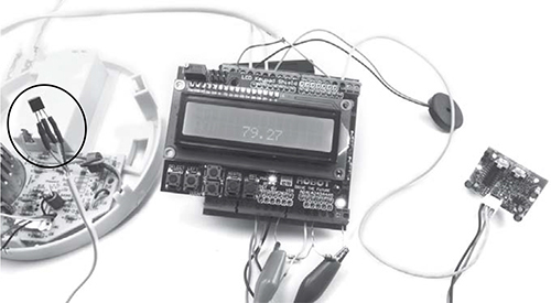
Figure 7-11: A fully laden Arduino, complete with temperature sensor (circled), movement detector, smoke alarm, and battery monitor
A three-pin temperature sensor is on the left of Figure 7-11, over the remains of the smoke alarm from Project 11. That sensor will send the Arduino temperature data, which the Arduino will then display as human-readable text.