Figure 6-13: Wiring diagram for the door sensor
Connect the reed switch to the D12 and GND terminals of the screwshield (it doesn’t matter which side goes where), connect the buzzer’s positive lead to D11, and connect the buzzer’s negative lead to GND. Note that both the negative connection of the buzzer and one connection of the reed switch go to the same GND screw terminal. Figure 6-14 shows the completed project, combined with the resistors used in Project 4.
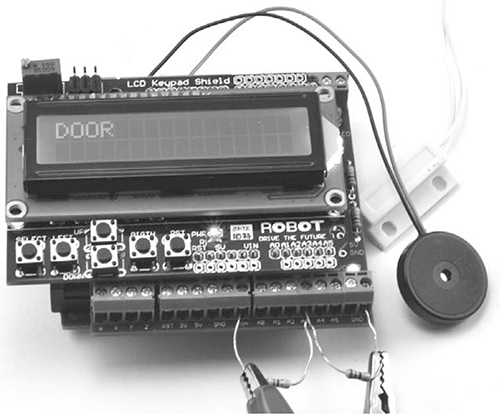
Figure 6-14: The completed door sensor
The alligator clips at the bottom of Figure 6-14 lead off to the battery, as described in Project 4. With the reed switch hooked up, let’s move on to the sketch.
SOFTWARE
All the source code for this book is available online at http://www.nostarch.com/zombies/. (See “Installing the Antizombie Sketches” on page 248 for instructions on installing the programs.) If you just want to make this project on its own, without any of the earlier Arduino-based projects, then use the sketch Project_10_Door_Sensor. If, on the other hand, you have made one or more of the earlier Arduino projects, then use the sketch All_Sensors and change the constants at the top to select the projects that you have made. See the comments section in the All_Sensors sketch for instructions on what changes to make.
The code follows the same pattern as Project 4, so for more information on how the program as a whole works, please refer to “Software” on page 57. Here, I will describe just the code specific to this project.
First, a new constant is defined for the Arduino pin that will act as an input for the reed switch.
const int doorPin = 12;
There is a new line of code in the setup function to initialize that newly defined doorPin (pin 12 on the Arduino) to be an input.
pinMode(doorPin, INPUT_PULLUP);
The type of input is specified as INPUT_PULLUP so that the input pin will be HIGH by default and only go LOW when the reed switch is closed by being near the magnet. The loop function now also calls a function named checkDoor, which contains the rest of the code for checking for the door being opened.
void checkDoor()
{
if (digitalRead(doorPin))
{
warn("DOOR");
}
}
The checkDoor function first reads the door pin. If the result of this read is HIGH, then the magnet is not close enough to the reed switch to hold the switch closed, and the input is in its default state of HIGH. Since the magnet isn’t next to the reed switch, the door must be open.
If you only need to know that the door has opened, you don’t need a continuous alarm, so checkDoor calls the function warn (passing it "DOOR") rather than alert, which you used for the battery monitor.
void warn(char message[])
{
lcd.setCursor(0, 1);
lcd.print(message);
delay(100);
lcd.setCursor(0, 1);
lcd.print(" ");
if (!mute)
{
tone(buzzerPin, 1000);
➊ delay(100);
noTone(buzzerPin);
}
delay(100);
}
The warn function is like alert: warn takes a message as an argument, prints that message to the LCD, and makes a sound. The difference is that the buzzer tone is cancelled with noTone after just a tenth of a second delay ➊, to give only a short beep when the door is opened.
USING THE DOOR SENSOR
It is always worth testing out a project on your workbench before you install it for real, especially when your life depends on the device working. If this door sensor fails, you could be zombified in your sleep! So first, load your sketch onto the Arduino and line up the reed switch and magnet close together. Then when you move them apart, the buzzer should go off.
Once you’re sure everything works as it should, affix the reed switch to the door frame and the magnet to the door. The magnet and reed switch should be opposite each other but not touching. It is best to have the magnet on the door rather than the frame, because the frame doesn’t move and will not flex the wires, which would shorten their life. Figure 6-15 shows the reed switch and magnet installed on a door.
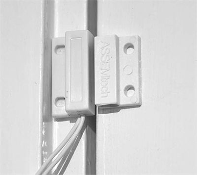
Figure 6-15: Reed switch and magnet on a door
Note that both the reed switch and magnet are often supplied with adhesive pads on the back to stick them to the door as well as mounting holes, so you can attach them to the wall nonpermanently, as I’ve done. However, if you are still worried about home decor after the zombie apocalypse, be warned that the adhesive may damage the paint when you remove the reed switch and magnet.
With your new monitor installed, you are ready to take the next step in making your base secure. In Chapter 7, you’ll connect smoke and temperature alarms to your hard-working Arduino to protect yourself from more natural disasters that might occur—as if zombies aren’t enough!
7
ENVIRONMENTAL MONITORING

Zombies are pretty frightening, but they’re not the only threat in a postapocalyptic world. More mundane risks like fire are especially serious if you can’t safely leave your compound (see Figure 7-1). In this chapter, I’ll show you how to build a fire alarm and a temperature alarm that alert you to environmental hazards—without alerting the zombies.

Figure 7-1: No smoking!
PROJECT 11: QUIET FIRE ALARM
Normally, you want a fire alarm to be as close to you as possible and as noisy as possible. But there’s one problem with loud alarms: zombies can hear. The last thing you want when escaping a burning building is to attract unwanted attention from passing zombies!
This project modifies a regular battery-operated smoke detector so that it registers an alarm on the Arduino display and sounds a much quieter buzzer, using the basic setup from “Project 4: Battery Monitor” on page 53. Figure 7-2 shows the smoke detector connected directly to the screwshield.

Figure 7-2: Testing the finished fire alarm. In your base, the detector will be connected to the Arduino by a long lead.
WHAT YOU WILL NEED
To make this project, you’ll need the Arduino and screwshield that you used in “Project 4: Battery Monitor” on page 53 as well as the following parts:
ITEMS
NOTES
SOURCE
Battery operated
Hardware store, Supermarket