WHAT YOU WILL NEED
To make this project, you’ll need the Arduino and screwshield that you used in “Project 4: Battery Monitor” on page 53 and the following parts:
ITEMS
NOTES
SOURCE
Temperature sensor
Adafruit (165)
To connect the sensor chip to the Arduino screwshield
Scavenged telephone cable or other three-core wire.
3 lengths of about an inch (25 mm)
Auto parts store
You could use electrical tape instead of heatshrink for this project, but I recommend heatshrink because it’s a lot tougher and not prone to unraveling.
CONSTRUCTION
Figure 7-12 shows the wiring diagram for the project. The LCD should be attached from an earlier project, so the only new part you’ll add is the TMP36 temperature sensor.
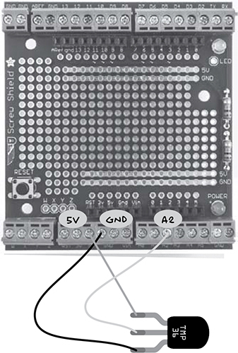
Figure 7-12: The wiring diagram for the temperature alarm
TMP36 TEMPERATURE SENSOR
The TMP36 is a handy little temperature sensor chip. It has three pins, and in this project, they’re connected to 5V, GND, and A2 on the Arduino. Figure 7-13 shows the pinout of this chip. These chips are only accurate to about 2 degrees Celsius. If you want greater accuracy, then you could consider changing this project’s design and software to use a digital temperature sensor like the DS18B20.
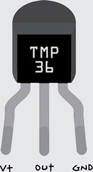
Figure 7-13: The TMP36 pinout
The positive supply voltage to pin V+ on the TMP36 can be anything between 2.7V and 5.5V. On its middle pin, the chip produces an analog output voltage proportional to the temperature. The temperature of the chip (in degrees Celsius) can be calculated from the voltage at the Out pin by this formula:
Temperature = 100 × volts - 50
So, if the voltage were 0.6V, the temperature would be 100 × 0.6 - 50 = 10 degrees Celsius. If you prefer your temperatures in degrees Fahrenheit, then just make one further calculation:
°F = °C × 9/5 + 32
The TMP36 can measure temperatures in the range -40 to +125 degrees Celsius, but the measured temperature is accurate only to within 2 degrees Celsius of the actual temperature.
STEP 1: MAKE A LONGER LEAD FOR THE TMP36
To extend the lead of the TMP36, you could just solder a three-core wire to it. However, to make it a bit more durable, you can use heatshrink tubing on top of the soldered connections. Figure 7-14 shows the process.
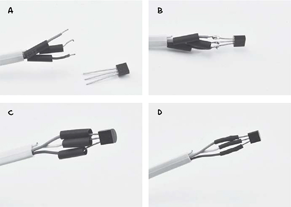
Figure 7-14: Using heatshrink on the TMP36 lead
First, strip the wires of each lead and slip the cut lengths of heatshrink over the individual wires (Figure 7-14a). Next solder the wires to the leads of the TMP36 (Figure 7-14b). Slide the heatshrink up over the solder joint (Figure 7-14c) and finally apply a hair dryer or hot air gun to the heatshrink until it, well, shrinks (Figure 7-14d). If you have wide diameter heatshrink, then you could place this around the whole sensor and individual leads to make this build more durable.
NOTE
For more information on using heatshrink, see the “Using Heatshrink” on page 235.
STEP 2: ATTACH THE TEMPERATURE SENSOR LEAD TO THE SCREWSHIELD
Attach the wires from the temperature sensor to the screwshield (Figure 7-11). You don’t have to use the GND connection shown; any of the GND terminals on the screwshield will do.
SOFTWARE
If you want to make this project on its own, without any of the earlier Arduino-based projects, then open the sketch Project_12_Temperature from this book’s source files and load it on to your Arduino now. If, on the other hand, you built one or more of the earlier Arduino projects, then use the sketch All_Sensors and change the constants at the top to select the projects that you have made. See the comments section in this sketch for instructions on this.
NOTE
All the source code for this book is available from http://www.nostarch.com/zombies/. See “Installing the Antizombie Sketches” on page 248 for instructions on installing the programs.
This code follows the same pattern as Project 4, so for more information on how the program as a whole works, please refer to “Software” on page 57. Here, I’ll just describe the code specific to this project.
First, a new constant is defined for the Arduino pin that will act as an analog input for the TMP36:
const int tempPin = A2;
Two more constants are defined to set the maximum and minimum temperatures allowed before an alarm is triggered. These are floats rather than ints because they represent decimal numbers rather than whole numbers.
// Project 12 constants
// these can be in C or F
const float maxTemp = 45.0;
const float minTemp = -10.0;
As the comments above the constants state, these temperature values can be in either Celsius or Fahrenheit. The units that the temperature is measured in are decided by a new function you’ll define.
The main loop function now includes a call to checkTemp, too. This function is defined as follows:
void checkTemp()
{
float t = readTemp();
if (t > maxTemp)
{
alarm("HOT", t);
}
else if (t < minTemp)
{
alarm("COLD", t);
}
}
The checkTemp function first calls readTemp to measure the temperature and then compares that with the maximum and minimum temperatures. If the temperature is too high or too low, then the alarm function is called. Note that this version of the alarm function has an additional parameter that is used to display the temperature on the LCD screen.
The readTemp function is where the raw analog input reading from the TMP36 is converted into a temperature.
float readTemp()
{
int raw = analogRead(tempPin);
float volts = raw / 205.0;
float tempC = 100.0 * volts - 50;
float tempF = tempC * 9.0 / 5.0 + 32.0;
// One of the following two lines must be uncommented
// Either return the temperature in C or F
return tempC;
// return tempF;
}
The raw value returned by analogRead is a number between 0 and 1023, where 0 indicates 0V at the analog input pin and 1023 indicates 5V. This voltage is calculated by dividing the raw value by 205 (205 is roughly 1023/5).