The code for the other fields displayed in the window is defined in the same way.
Of course, you may want to use more—or less—descriptive labels, so change them to anything you like. For more information on formatting with the Tk graphics library, see http://tkinter.unpythonic.net/wiki/.
COMMUNICATING WITH THE ARDUINO
At the end of the __init__ method you will find these two lines:
self.ser = serial.Serial(PORT, BAUD, timeout=1)
time.sleep(2)
The first of these lines opens serial communication with the Arduino. The second pauses for two seconds to allow the Arduino time to start up before any messages are sent to it.
KEEPING YOUR CONTROL CENTER UPDATED
If the displayed values don’t automatically update, your control center is pretty useless. Updating is accomplished with the read_arduino method.
Here is the first part:
def read_arduino(self):
self.ser.write('?')
volts, temp, door, pir, fire = self.ser.readline().split()
self.volts_var.set(volts)
self.temp_var.set(temp)
self.door_var.set(door)
self.pir_var.set(pir)
self.fire_var.set(fire)
The read_arduino method first sends the ? command to the Arduino, which responds with a line of values separated by spaces, as you saw when trying out the Arduino code in the serial monitor. The returned string of values is then split up, using the spaces as a delimiter (this is the default delimiter for the .split() function). StringVars associated with each field in the window are then updated in the display.
After the values are updated, the remainder of the read_arduino method sets the color of the fields to red or green as appropriate.
To ensure that the read_arduino method is called at regular intervals, it is necessary to schedule a call to it from the Tk user interface object:
def update():
app.read_arduino()
root.after(500, update)
root.after(100, update)
This code ensures that after 100 milliseconds (1/10 second), the function update will be called. The function update first calls read_arduino and then schedules itself to run again in 500 milliseconds (half a second), meaning that our control center checks all of our sensors every half second. If you’re in danger, whether from zombies or environmental hazards, you’ll know quickly!
You can run this program at the same time as you run the USB webcam of “Project 7: Monitor Zombies with a USB Webcam” on page 87 by opening two LXTerminal windows and running one program in each terminal window. That way, you can see instantly what might have triggered your alarms.
USING THE CONTROL CENTER
Now, you have a screen that will give you continuous updates on all of the safeguards of your stronghold. Place your control center somewhere you can easily see it, and if you’ve included all of the components from Figure 8-3, you’ll know instantly if your supplies are in danger, if your power supply is running low, and if zombies have breached your perimeter.
If you find that the user interface values do not update, then go back to “Arduino Software” on page 143 and again test the Arduino using the serial monitor by sending the ? command to look for a status response in the serial monitor.
PROJECT 14: GOING WIRELESS WITH BLUETOOTH
The control center of Project 13 is bogged down in wires right now, and you have to keep the Arduino and the Raspberry Pi together. That also means that you’ll probably only know that, say, your base has caught on fire once the flames have reached you—and then it will be too late. You can make your control center much more effective by connecting the Raspberry Pi and the Arduino wirelessly over Bluetooth, as we’ll do in this project, so your sensors can detect danger before it reaches you and your monitor.
The Raspberry Pi does not have Bluetooth built in, but it will accept a wide range of Bluetooth USB dongles. We’ll add Bluetooth to the Arduino using a Bluetooth serial module, shown sticking out at the right in Figure 8-6.
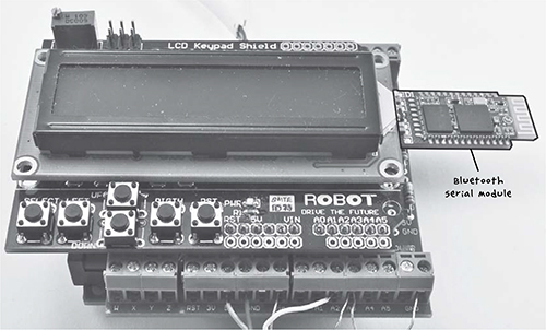
Figure 8-6: Adding Bluetooth to an Arduino
To make this project, first complete “Project 13: A Raspberry Pi Control Center” on page 140 and make sure that everything else is working properly. Then you’ll be ready to add the wireless link.
WHAT YOU WILL NEED
To make this project, you are going to need everything from Project 13 plus the following parts:
ITEMS
NOTES
SOURCE
Compatible with Raspberry Pi
Computer store, eBay
HC-06 Bluetooth serial module
eBay
Mouser (293-270-RC)
Mouser (293-470-RC)
4-way
Adafruit (392), eBay
Adafruit (196)
For making connections on the prototyping area of the screwshield
Adafruit (1311), scavenge
(Optional) Would replace header pins
Adafruit (266)
The hardware for this project can be built onto the screwshield that you have used while building up the various sensor projects (4, 6, 10, 11, and 12) that use a screwshield. The Bluetooth module I used is a Cambridge Silicon Radio (CSR) device. For a list of Bluetooth dongles compatible with the Raspberry Pi, visit http://elinux.org/RPi_USB_Bluetooth_adapters/. If you are worried about soldering the Bluetooth module directly to the header pins, then you may prefer to use four female-to-female jumper wires to link the header pins to the Bluetooth module.
NOTE
You can save yourself some tricky soldering by looking for a module and adapter pair that already has the module soldered into place.
A lot of the Bluetooth HC-06 modules have six rather than four pins. The pins you will be using are +5V, GND, TXD, and RXD, so you can ignore the other two. These are usually the outside pins, but do check the pinout names as occasionally some designs swap the pin positions around.