CONSTRUCTION
Figure 9-3 shows the wiring involved in this project.
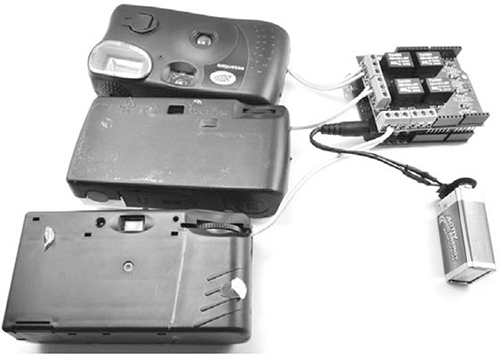
Figure 9-3: The flash distractor, spread out
Each of the disposable cameras has a short length of double-core wire leaving one side of its case. These wires connect to the switch contact inside the camera that is used to trigger the flash. I’ll describe how to create this setup for one camera in construction Steps 2 to 5, and you’ll need to repeat those steps for all three cameras.
Each pair of leads connects to one pair of relay contacts on the shield so that the Arduino can trigger each flash independently.
Each camera also has its own AA or AAA battery that powers the flash, while the Arduino and relay shield are powered from a 9V battery connected to the DC barrel jack of the Arduino. This makes the project completely portable, so you can place it wherever needed to create a distraction that lets you escape.
STEP 1: SORT THE CAMERAS
First, sort your bag of cameras by type. To make this project simpler to build, try to pick out three identical cameras. The modules I used were all Fujifilm, though the branding on the cardboard covers differed.
WARNING
Do not try out the Flash of the camera at this stage! It will charge the camera’s capacitor, and you’ll get shocked later when you lever the camera body apart with your fingers. seriously, this really hurts!
STEP 2: REMOVE THE TOP CASING FROM A CAMERA
Used cameras may have already been partly disassembled when the photo processor removed the 35mm film canister. The processors do this quickly rather than tidily, so there’ll probably be cardboard and bits of plastic hanging off. Figure 9-4 shows the steps involved in taking a camera case apart.
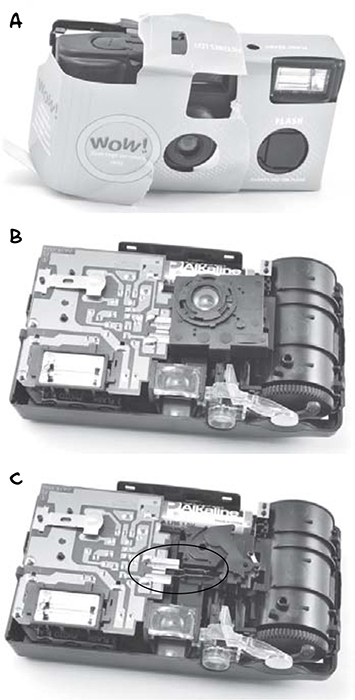
Figure 9-4: Disassembling a camera
You are at risk of shock during this step, so take care not to touch the circuit board or any contacts or wires within the camera.
First, remove the cardboard from the camera body (Figure 9-4a). Next, use a flathead screwdriver with a plastic handle (to provide insulation from shock) to lever apart the plastic catches holding the two halves of the camera body together. Remove the front half of the camera case, exposing the PCB and lens (Figure 9-4b). Now remove the lens assembly. Break it off if you have to; it’s not needed anymore. This will expose the two contacts shown circled in Figure 9-4c, which fire the flash when they are touched together.
STEP 3: MAKE THE CAMERA SAFE!
Before you have rendered the camera module safe, treat it the same way you would a small but vicious rodent. Don’t handle it directly. If you need to move it around or flip it over, poke it with something like a plastic pen. Otherwise, you might injure yourself, and you need to be in top condition to stay ahead of the zombies.
Identify the flash module’s capacitor. The capacitor will be a large metallic cylinder with two leads connecting it to the PCB. The capacitor stores all the energy that is rapidly discharged into the flash to set it off. In Figure 9-5, the entire flash module has been removed from the camera body to make it easier to see the capacitor, but follow the capacitor discharge steps below without removing the whole PCB if you can.
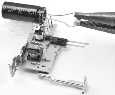
Figure 9-5: Discharging the capacitor
To discharge the flash module’s capacitor, bend the legs of your 100 Ω resistor so they are roughly as far apart as the legs of the capacitor. Gently grip the body of the resistor with pliers (with insulated handles) and touch the resistor leads across the capacitor leads. If the capacitor is charged, there will probably be a very small spark. Hold the resistor in place for a second or so to make sure the capacitor actually discharges.
Now, check whether the capacitor is empty by measuring the voltage with your voltmeter set to its maximum DC voltage range. (The voltage range needs to be 500V or more.) It doesn’t matter if there are a few volts left in the capacitor, but if you see more than 10V, then discharge it a bit longer with the resistor. Once the voltage is below 10V, it is safe for you to handle the PCB without fear of electrical shock.
STEP 4: ATTACH LEADS TO THE TRIGGER CONTACTS
Solder about 6 inches (15 cm) of double-core wire to the flash contacts, as shown in Figure 9-6. In the camera I used, there was a handy plastic peg that allowed the two contacts to be kept well apart. If this is not the case for your camera, then you may need to wrap the soldered contacts in electrical insulating tape or put heatshrink over the contacts to keep them apart.
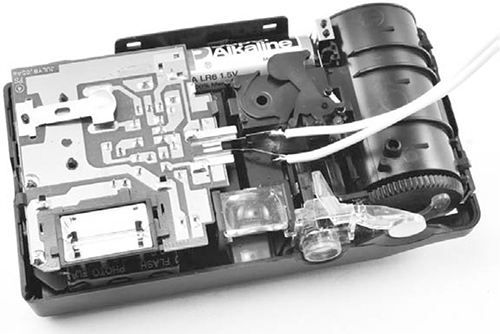
Figure 9-6: Leads soldered to the trigger contacts
STEP 5: REASSEMBLE AND TEST THE MODIFIED FLASH MODULE
Fit the front cover of the camera back on, allowing the double-core wire to escape through one side of the camera. If you need more space to snake the wires out, use a pair of diagonal cutters to cut a hole in the plastic cover.
Test this flash before repeating the procedure for the other two cameras. The trigger contacts of these cameras are sometimes at 400V, so for safety, use a screwdriver with an insulated handle.
Turn on the flash switch for the camera. You should see a charging light or LED come on. The camera will probably make a whining noise as the flash charges. This sound is created by the capacitor filling up. When you think the charging is complete (or after, say, 10 seconds), use the screwdriver to connect the two trigger leads, as shown in Figure 9-7.
The camera should flash when you connect the leads with the screwdriver. Hurray! That’s one camera ready for action. Before moving on to Step 6, repeat Steps 2 through 5 for the other two cameras.
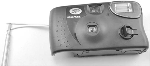
Figure 9-7: Testing the modified camera
STEP 6: CONNECT THE CAMERAS TO THE RELAY SHIELD
Fit the relay shield onto your Arduino, making sure that all the pins of the shield engage properly with the sockets on the Arduino.
Figure 9-8 shows how the cameras are wired up to the relay shield.
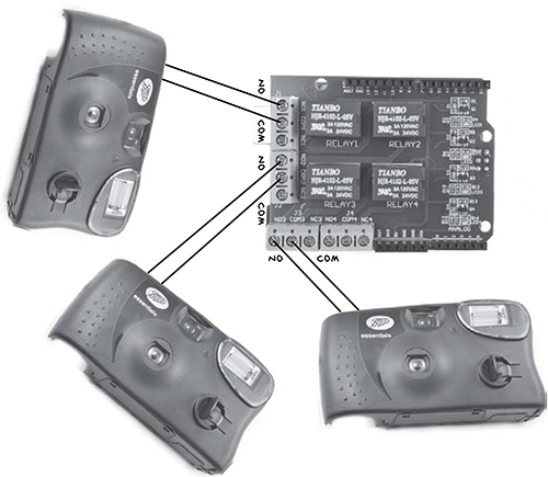
Figure 9-8: Attaching leads from the cameras to the relay shield’s trigger contacts
Each relay on the relay shield has three screw terminals: NO, COM, and NC. When the relay is not activated, the terminals NC and COM are connected, but when the relay is activated, COM becomes connected to NO. This means that the leads to each camera need to go into the COM and NO connections of each relay. It does not matter which way around the leads go.
When your cameras are connected to their relays, attach the battery clip–to–barrel jack adapter to the Arduino, as shown in Figure 9-9.
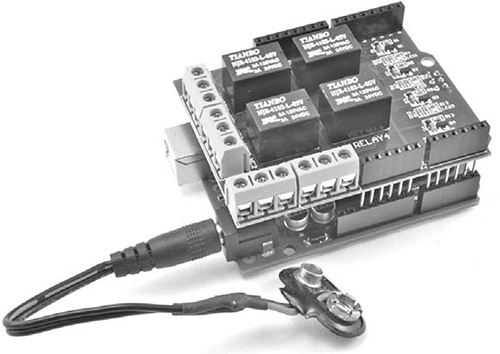
Figure 9-9: Attaching the battery lead to the Arduino
Before attaching the battery itself, however, you need to upload the software for the project, so you may as well power the Arduino from the USB lead while you program it.
SOFTWARE
All the source code for this book is available at http://www.nostarch.com/zombies/. Visit the link provided there and download the code now, if you’ve not done so already. See Appendix C for instructions on how to install the Arduino sketch.
The Arduino sketch for this project is called Project_15_Flasher, and it’s in the source file directory of the same name. I’ll walk you through this sketch now.