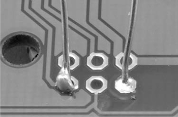
Figure B-7: Bad (left) and good (right) solder joints
USING HEATSHRINK
When you’re confident in your wire-connecting skills, try using heatshrink to insulate the wires. Heatshrink is a great way to finish a pair of wires that have been joined by twisting or soldering, and it’s a lot more durable than electrical tape. Wrapping the wires in electrical tape is fine at first, but eventually the tape starts to lose its stickiness and unravel. Heatshrink is also just more fun to use, and you’ll need all the fun you can get when zombies are the only ones knocking on your door.
Heatshrink comes as a tube that you can cut to the length you need. When heated with a hair dryer, hot air gun, or even a cigarette lighter, it shrinks to about half its diameter as if by magic. If your heatshrink starts out with a fairly snug fit over the wires, then it will grip the wires tightly after you heat it.
Here’s how to make a good connection and strengthen it with heatshrink:
1. Choose a heatshrink tube slightly wider than the joint you want to cover. Cut a sleeve long enough to cover the exposed wire and overhang onto the wire’s insulation a little bit.
2. If you’re connecting two wires that already have parts attached to their other ends, slide your heatshrink sleeve onto one wire before you solder them together, pushing the heatshrink as far away from the solder point as possible. I’ve lost count of the number of times I have soldered something together only to remember too late that the heatshrink then couldn’t be slid on. Every time that happens, I have to unsolder the wires again.
3. Join the wires using the end-to-end method described in “Joining Wires with Solder” on page 231. You’ll end up with something like Figure B-8a.
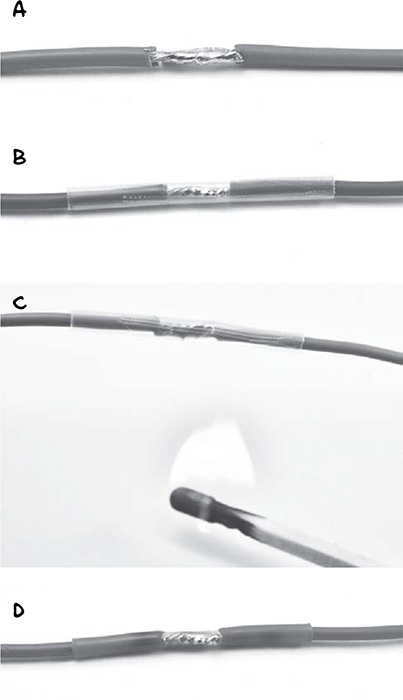
Figure B-8: Applying clear heatshrink tubing over joined wires
4. If you haven’t already done so, slide the heatshrink sleeve over the joint (Figure B-8b). The heatshrink I show is clear so you can see that the solder joint is good. Heatshrink is also commonly available in black and other colors.
5. Heat up the heatshrink with a hair dryer or even a match held underneath it (Figure B-8c). You don’t need to make it super hot. Just keep heating until you have a nice tight fit, as in Figure B-8d. But try not to scorch it!
Heatshrink comes in a huge range of diameters. If you plan to use it, I suggest buying a selection box that has short lengths of various diameters of heatshrink tubing. You can find these at auto parts stores, as heatshrink is often used when modifying or repairing car wiring.
USING A MULTIMETER
An electric current is a flow of electrons. But electrons are small—very small, in fact. So when it comes to working out what’s going on electrically, we need something that will allow us to measure what those pesky electrons are up to.
Where a doctor has a stethoscope to check the various pulse points in your body, an electronics enthusiast will use a multimeter (Figure B-9) to check specific points on a circuit.
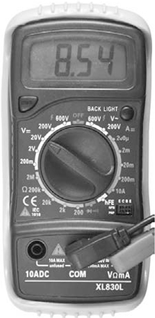
Figure B-9: A multimeter
The multimeter shown in Figure B-9 cost about $5 but is still more accurate and has a wider range of features than an expensive multimeter from 20 years ago. Something like it should be perfectly good for any current, voltage, or resistance you need to measure to get ready for the zombie apocalypse.
A multimeter consists of a display at the top, a big rotary switch in the middle to select different measurement ranges, and some sockets at the bottom for attaching test leads. A multimeter should include test leads when you buy it. These are usually of the sort shown in Figure B-10a, but it can be very useful to also get some test leads that have alligator clips on the end (Figure B-10b).
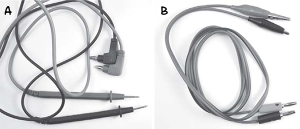
Figure B-10: Test leads
Most auto parts stores will have multimeters, and many places where you can buy tools might well have a multimeter or two. Amazon and eBay also have a huge array of low-cost multimeters for you to choose from, if you want to stock a couple in your apocalypse preparedness kit.
MEASURING DC VOLTAGE
Multimeters are most commonly used to measure DC voltage. This is what we would do to, say, check the voltage of a battery (Figure B-11).
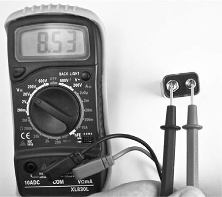
Figure B-11: Measuring DC voltage with a multimeter
If the battery says on the case that it’s a 9V battery, but when you measure the voltage across its terminals you get a reading of 4V, then there is something wrong with the battery. The 9V battery in Figure B-11 measures 8.53V, which is perfectly normal. If it’s under 8V, you should probably toss it.
To measure the voltage of a battery, follow these steps:
1. Set the range knob of the multimeter to DC volts and pick a range that is higher than the highest voltage you are expecting. For a 9V battery, for example, the 20V range is a good choice. (Multimeters also have an AC voltage range. The AC ranges have a wavy line next to them, and the DC ranges have one horizontal line above another.)
2. Make sure that the test leads are in the sockets for voltage measurement and not for current measurement. The black lead should be plugged into the COM socket, and the red lead should be plugged into the socket marked with a V. This is important because when measuring current, the multimeter leads are almost a short circuit and using a currentconfigured meter to measure voltage would cause a short circuit across the battery. This is likely to blow a fuse in the multimeter.
3. Connect the black COM lead to the negative end of the battery and the red positive lead to the positive terminal of the battery. The multimeter’s display will tell you the voltage.
In addition to measuring the voltage of a battery to find out whether it’s good, you may want to measure the voltage across a component, say an LED or resistor. In that case, just touch the probe leads to either side of the component.
MEASURING DC CURRENT
When you need to maximize the life of your battery, which will be important when the apocalypse is on, it’s often useful to see how much current a device is using. As an example, we could test how much current will be drawn by an Arduino.
Figure B-12 shows a multimeter set up to test the current consumption of an Arduino powered from a 9V PP3 battery. A barrel jack lead is used to connect the 9V battery. The multimeter sits in the circuit, measuring the current flowing through it (in this case 32.6 mA). The positive terminal of the battery is connected to the positive lead of the multimeter, and the rest of the circuit (or in this case the Arduino) receives its power through the negative lead of the multimeter.
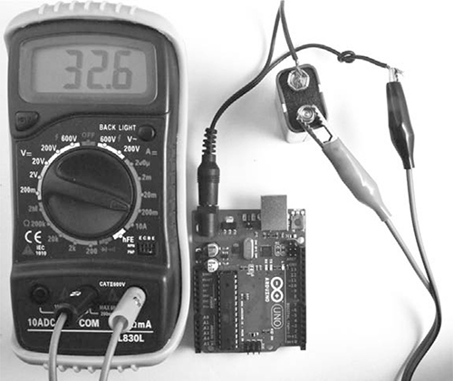
Figure B-12: Measuring DC current with a multimeter
Follow these steps to measure current:
1. Set the range knob of the multimeter to a DC Amps range. On its own, an Arduino only uses about 30mA of current, so select the 200mA range. If in doubt, start with the maximum range (often 10A) and work down if you need more precision.
2. Make sure that the positive test lead is in the correct current measuring socket on the multimeter. For low currents (about 200mA or less), this is often the same connection that’s used to measure volts. The multimeter shown here has a separate socket for currents up to 10A, but since we shouldn’t see more than 30mA, the voltage socket is being used.