Field connection (D+) On my alternator, this is labeled D+, although it is just as common for it to be labeled F.
STEP 4: WIRING
Now that you know which terminal of the alternator is which, you need to make some leads to connect everything together. The wiring diagram shows how to do this (Figure 2-17).
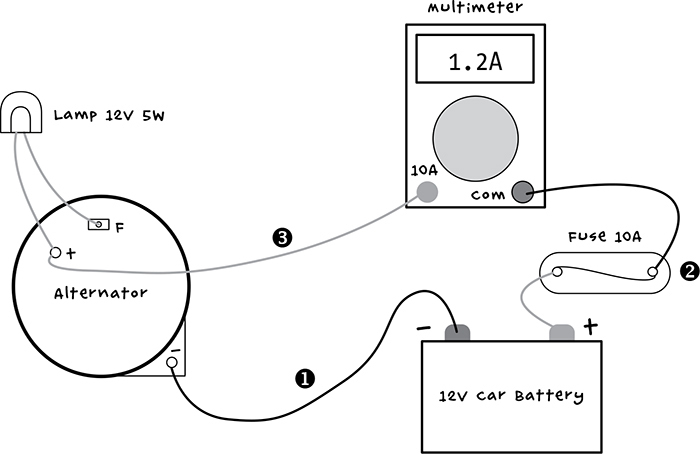
Figure 2-17: Wiring diagram for the cycle charger
The light bulb serves two purposes. It limits the current to the field coil so you don’t have to pedal too hard to kick-start the alternator into generating. The bulb also serves as a useful indicator: when the alternator starts generating, the light will go out.
There are a few leads to make. Let’s start with the lead from the negative terminal of the alternator to the battery negative terminal (➊ in Figure 2-17). This needs a large alligator clip on the battery end and a butt connector on the other, as shown (Figure 2-18).

Figure 2-18: The negative battery lead
You could use any black wire for this lead, but I used two-thirds of a black multimeter lead, from the probe end of the multimeter, and cut off the probe itself. Strip about half an inch (10 mm) of the insulation off each end of the wire. The butt terminal can be crimped (squeezed with pliers) onto the lead. Attach the alligator lead by wrapping the stripped wire clockwise around the bolt before tightening up the bolt.
This charging circuit doesn’t include a charge controller to protect it, so you’ll need a fuse. Fuses are short lengths of metal designed to melt and so break a connection when too much current flows through them. A car battery can store quite a lot of energy—enough to start a fire—so it’s worth using a fuse. If something should accidentally short out, the fuse will blow, breaking the connection before too much damage is done.
The most convenient type of fuse holder has trailing wires at each end. You can use these trailing wires to make the lead between the positive terminal of the battery and the multimeter (➋ in Figure 2-17). Attach an alligator clip lead to one fuse wire and attach the remaining third of the black multimeter lead to the other fuse wire. Wrap the connection between the fuse and multimeter leads with electrical tape, and you should have the completed lead (Figure 2-19).
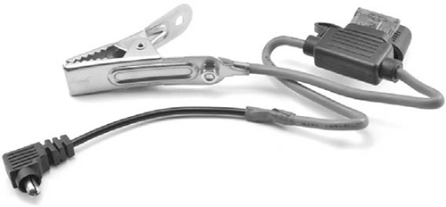
Figure 2-19: The fuse lead
The final of the three leads (Figure 2-20 and ➌ in Figure 2-17) combines both the lamp and the positive charging connector from the alternator to the multimeter.
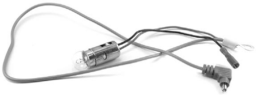
Figure 2-20: The positive charging and light bulb lead
As with the fuse holder, I used a light bulb holder with trailing leads. Crimp a ring terminal of the correct size for the F connection of the alternator. It’s best to use an insulated spade terminal to minimize the chances of a short circuit.
Chop off the probe from the red multimeter lead, strip half an inch (10 mm) of insulation off the lead, and twist the bare wires together with the other lead of the light bulb holder. Crimp the combined wires together into the butt terminal for the positive charging connection of the alternator.
STEP 5: FINAL ASSEMBLY
With all the leads prepared, it’s time to connect everything according to the diagram in Figure 2-17.
The photograph shows the alternator, battery, and multimeter all wired up (Figure 2-21). Before you connect the battery and alligator clip, make sure the multimeter is set to its maximum current range and that the correct sockets for maximum DC current are being used.
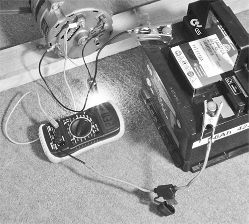
Figure 2-21: The completed wiring
GENERATORS
A noisier way to generate electricity is to use a gasoline generator. One of these can be found fairly readily and will generate high-voltage AC to directly power normal AC devices. The problem with generators is that they require a constant supply of fuel, make considerable noise, and generate exhaust fumes that must be vented outside.
They’re also quite heavy, so if you’re determined to bring one home, have enough people in your scavenging team to carry the generator, keep any lone zombies distracted, and clear a path when you inevitably encounter a mob of zombies right outside your base.
USING THE PEDAL GENERATOR
Before you start pedaling, the bulb should be on, and the multimeter should indicate a current of about –0.3A. The value is negative because this current is being used by the lamp.
Crank the pedals quite fast, and you should see the lamp start to dim and then extinguish. At this point, you’ll probably feel a lot more resistance from the pedals. This is good news: you’re generating electricity! The current should now show a positive value. With furious pedaling, this might increase to 2A or 3A.
If your battery is fully charged, then the bulb should go out while the current remains at zero. This is because the alternator includes a voltage regulator circuit that stops charging the battery when it’s up to its maximum voltage. If you need to discharge the battery a little to test that it charges, then you might want to move on to the next project—where we start using some of the energy that we’ve stored in the battery—and return to test this project later.
You should only connect the charging circuit when you are ready to start using it, as the light bulb will eventually drain the battery completely.
Once you’ve successfully built one pedal-powered generator, you can repeat these instructions to build a charging station for each person in your base. By generating electricity as a team, you’ll stockpile plenty of batteries, and everyone will be able to contribute to your group’s continued survival!
We’ve thoroughly explored a few ways of generating electricity and, in particular, charging up car batteries. In the next chapter, you will learn how to start using this electricity and monitor the state of your batteries so that you don’t suddenly get plunged into darkness.
3
USING ELECTRICITY

Now that you have a neat row of car batteries all charged up and ready to use, it’s time to use them to improve your standard of living (see Figure 3-1). First, you’ll learn how to connect those batteries to something useful, and then in this chapter’s first project, you’ll build a simple lighting circuit.
The second project in this chapter will show you how to use an Arduino microcontroller board and a few extra components to make a simple battery monitor. You wouldn’t want to lose your brains just because your defenses’ batteries died!

Figure 3-1: Car batteries have a variety of uses in the postapocalyptic world.
POWERING DEVICES FROM A CAR BATTERY
Let’s look at how you can use all that energy to make your life more comfortable while you keep those pesky zombies at bay. Of course, you first have to get the electricity from the battery to your device. There are two common connectors you’ll want to have on hand.
CIGARETTE LIGHTER SOCKETS
As DC voltages go, 12V is pretty useful. It’s the same voltage you find in the cigarette lighter socket of a car, and there are lots of 12V appliances that you can just connect straight to the battery. This includes various types of lighting, fans, drink warmers, air compressors, DVD players, mini fridges, and more.
In fact, there are so many 12V appliances with a cigarette lighter plug on the end that it’s worth making an adapter lead that will allow you to plug them right in, without having to modify them.