You may have to improvise with wooden batons to attach the panels. The photograph shows my solar panel mounted on a roof (Figure 2-6).
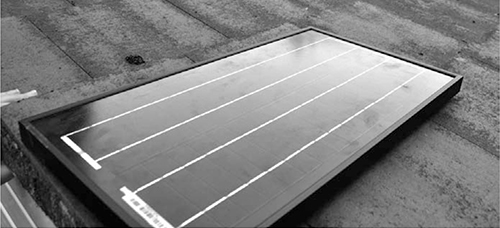
Figure 2-6: Solar panel ready to make power
STEP 2: ATTACH A LEAD TO THE SOLAR PANEL
The solar panel may have screw terminals, or, as mine does, it may have a short length of wire soldered to its terminals. The lead attached to the solar panel needs to be long enough to reach inside your base, where you can ensure it stays dry. Attach a lead that can be fed through a hole on the wall or in the roof and attached to the screw terminals. Just like zombies, water is likely to find its way through any gap, so seal up holes after you have threaded the cable through. Silicone sealant works well for this.
Once the cable is inside, you can use the terminal block to extend it to the length you need, though a single length of cable without joins will be most reliable. A terminal block can be used to join the lead from the solar panel to a longer lead, which will be connected to the charge controller (Figure 2-7).
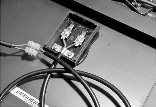
Figure 2-7: Connecting the solar panel
STEP 3: WIRE UP THE BATTERY AND CHARGE CONTROLLER
Wire up the battery, multimeter, and charge controller as shown in Figure 2-5. The red probe lead from the multimeter can fit in the screw terminal of the charge controller, but the black probe needs to connect to the battery somehow. The best way is to attach one end of the black probe to one of the heavy-duty alligator clips.
This means we need to make three leads, using the alligator clips and probe leads. For the first of these leads (labeled ➊ in Figure 2-5 and shown in Figure 2-8, I just used half of the multimeter’s black lead, with the probe cut off. However, you can use any black wire you like.
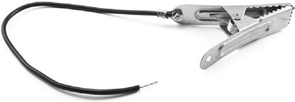
Figure 2-8: Negative battery lead
This lead will connect the battery to the negative (–) terminal of the charge controller. To make the lead, strip about half an inch (10 mm) of the insulation from each end of the wire. Connect one of those ends to the alligator clip by wrapping the wire clockwise around the loosened bolt on the clip. Then tighten the bolt so the clip grips the bare wire.
NOTE
The wire should be wrapped clockwise around the bolt so that when you turn the bolt, it pulls the wire around with it rather than pushes it away. The connection just works better that way.
Use a pair of pliers to wrap the supporting tabs at the end of the clip around the wire. These will prevent the wire from pulling off the clip if the wire is accidentally pulled on.
The second of the three leads (labeled ➋ in Figure 2-5 and shown in Figure 2-9) will go from the positive high-current terminal of the multimeter to the positive battery output of the charge controller. This lead is just the positive meter lead with the probe cut off and the insulation stripped off the last half inch (10 mm).
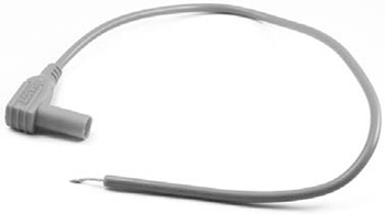
Figure 2-9: Positive charging lead
You’ll connect the final of the three leads (labeled ➌ in Figure 2-5 and shown in Figure 2-10) from the negative (COM) connection of the multimeter to the alligator clip that will be connected to the positive terminal of the battery.
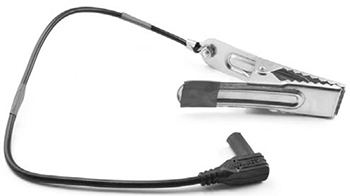
Figure 2-10: Positive battery lead
Strip about half an inch (10 mm) of insulation from the remainder of the black probe lead of the multimeter and attach it to the alligator clip in the same way you did for the lead ➋. This new lead is going to be connected to the positive terminal of the battery.
This lead is black, however, and since the convention is that black means negative, the color could be confusing. To make the purpose of this lead more intuitive, wrap some red electrical tape around it to make red stripes and add some red tape to the “finger end” of the alligator clip.
Now use the three leads to connect everything together, ready for use (Figure 2-11). Note that most multimeters have a special positive socket just for high currents. This may be labeled 10A or 5A. Plug the red lead into that socket. Be sure to set meter to the correct range, which is DC current at the meter’s maximum available current reading.
STEP 4: TESTING
To test the solar panel, use the highest DC amps setting of the multimeter to monitor how much current flows into the battery from the panel via the charge controller. If the battery needs charging, the charge controller should attempt to charge the battery as much as possible until it is full, and the meter should show a positive reading. After the battery is full, most charge controllers will switch to a trickle-charge mode that just keeps the battery topped up.
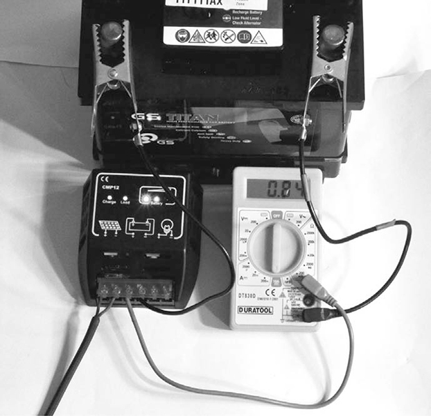
Figure 2-11: The charge controller, multimeter, and battery are connected.
In Figure 2-11, 0.84A of current is flowing into the battery. If your current reading is negative, then current is flowing out of the battery. This means something is wrong, so check over your wiring. You should also see the current drop considerably if you cover part of the solar panel or if the sun goes away.
If the battery doesn’t need charging, then the meter should read zero, which doesn’t tell you much. You’ll have to wait until Chapter 3, when we attach some lighting to the battery, to see the charging process in action.
USING THE SOLAR CHARGER
To ensure a continuous supply of electricity, it’s a good idea to duplicate this entire design so that if one solar panel or set of wiring should fail, you have a spare. Since swapping batteries just means unclipping the alligator clips, you can even keep a stack of batteries in rotation and set a few fully charged batteries aside for emergencies. Stockpile batteries for your own base, or start a new career as a postapocalyptic battery shop owner. Money might be useless, but I’m sure you could barter electricity for food, supplies, or assistance with your next scavenging trip.
On a sunny day, if lots of current is flowing from the solar panels, you may find that the alligator clips get hot. Wrapping some tape around them will reduce the chance that you’ll burn your fingers when you swap in a new battery.
PROJECT 2: BICYCLE GENERATOR
In this project, you’ll generate power with an adapted bicycle, which doubles as a great way to stay in shape so you can outrun the undead. The design uses a car alternator to charge the car battery. The alternator is just doing what it would naturally in a car, but without an engine. The alternator includes all that is needed to charge the car battery, so in this project, there is no need for the charge controller that you used in the solar project.
NOTE
You could also adapt this project to use other forms of rotary movement. For example, you could connect it to a wind turbine, a water wheel, or zombies on a treadmill (Figure 2-12).

Figure 2-12: Zombie power
WHAT YOU WILL NEED
To make this project, you will need the following items.
ITEM
NOTES
SOURCE