Large wheels
Scavenge
Almost any will work
eBay, Scavenge
12V
Auto parts store, Scavenge
V belt, size A100
Auto parts store, eBay, hardware store, scavenge
7A or more
Auto parts store
To suit your alternator terminals
Auto parts store
To suit your alternator terminals
Auto parts store
7A
Scavenge
Simple multimeter
Auto parts store, eBay, Fry’s
12V 5W lamp
Auto parts store
10A fuse and holder
Auto parts store
Hardware store
5 feet (1.5 m)
Hardware store
This is another project that uses a multimeter as a fixture, and I would again suggest you use the cheapest possible multimeter. You will probably also find it useful to have a spare multimeter to use for testing.
CONSTRUCTION
The trick to building this project is to keep the cycle’s back wheel away from the ground. There are two ways to do this. One is to make (or scavenge) a stand designed to allow a regular bike to be used as an exercise bike. This needs to be strong enough to support you when you sit on the bike, so a maintenance stand probably won’t be strong enough.
The other approach is to turn the bike upside down. Then you can use the pedals with either your hands or your feet while you sit in a chair near where the handlebars used to be. I used the upside-down bike approach.
ALTERNATORS
If you know a little about electronics, you may be aware that most DC motors can be used to generate current. Moving a coil of wire in a magnetic field (usually supplied by a regular magnet) will cause a current to be generated in that wire.
Alternators, like all generators, operate on this basic principle, but instead of a normal magnet, the magnetic field that the generating coil turns in is created by an electromagnet. The electromagnet is powered by the alternator itself once it gets going. To get going, the alternator must be connected to the battery; other-wise, there will no magnetic field for the generation to start. It’s a chicken-and-egg situation: the alternator needs to be generating current in order to generate current.
Figure 2-13 shows a simplified schematic of a car alternator.
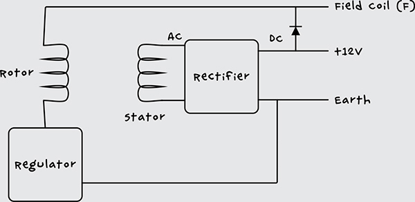
Figure 2-13: The schematic diagram for an automotive alternator
In actual fact, the alternator will normally have three stator coils producing three-phase AC to be turned into DC (unlike ordinary domestic two-phase AC). If you want to find chapter and verse on alternators, then take a look at the description at http://www.allaboutcircuits.com/vol_6/chpt_4/8.html.
STEP 1: MODIFY THE BICYCLE
First, strip off every piece of the bike that you don’t need. You can take away the front wheel, both mudguards, and the brakes. The gears can stay.
Remove the rear wheel and remove its tire and inner tube. Then place the drive belt over the wheel and fix the wheel back onto the bike.
STEP 2: FIX THE ALTERNATOR AND BIKE TO THE 2×4
Alternators don’t have standard positions for their fixing lugs, so you may have to improvise a little here. The drive wheel of the alternator needs to line up with the cycle’s wheel, but the alignment doesn’t need to be exact, especially if you use a long belt like the one in my final arrangement (Figure 2-14).
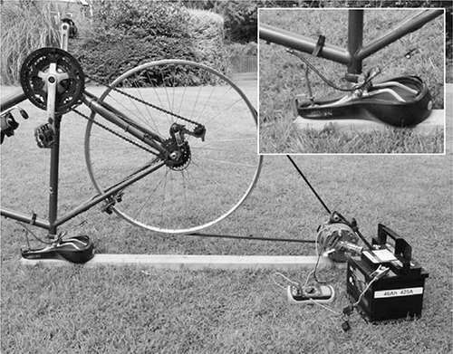
Figure 2-14: The mechanical arrangement of bike and alternator
Use a G-clamp to fix the bike to the 2×4 using the saddle. Adjust the saddle first so that it is flat. Alternatively, you could also remove the saddle completely and make a hole of the same diameter as the saddle stem partway through the 2×4.
Where you place the alternator on the 2×4 depends on the geometry of the alternator, the bike, and the drive belt, so I can’t give you exact measurements. Fix the alternator in place once the bike is attached to the 2×4 and the drive belt is around the cycle wheel. The alternator I used had a convenient hole that allowed it to be fixed to the side of the 2×4 (Figure 2-15). The drive belt doesn’t need to be under a lot of tension, but you can create a simple tensioner with a spring or elastic strap; you can even cut the latter from the discarded bike inner tube.
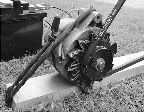
Figure 2-15: Attaching the alternator to the 2×4
Turn the cycle very gently to make sure everything is working mechanically and then move on to the next step.
WARNING
Don’t be tempted to try whizzing the alternator around at high speed without attaching the rest of the circuit, because generating high voltage in the coils with no load can damage the built-in electronics of the alternator.
STEP 3: IDENTIFY THE ALTERNATOR TERMINALS
Now that the mechanical part of the generator is built, we can start looking at the electrical side. First identify the connections on the alternator. Although they have slight differences, automotive alternators are remarkably standard, especially those from older cars. Plus, alternators are often easy to remove from older vehicles.
I used a reconditioned alternator that I bought on eBay for just a few dollars (Figure 2-16). Postapocalypse, however, there should be no shortage of abandoned old cars.
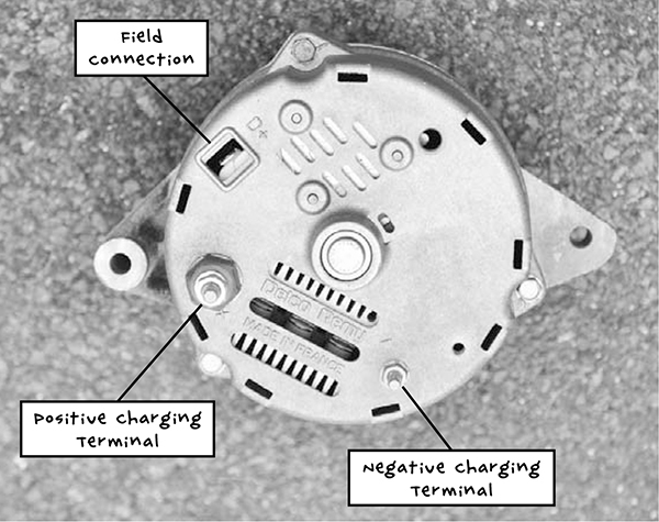
Figure 2-16: Delco LRA443 alternator (from the 1980s)
You are looking to identify three connections from the alternator:
Negative charging terminal (–) This will normally be connected electrically to the metal case of the alternator, but there should also be a bolt specifically for attaching a spade terminal. It may be marked –, GROUND, or GND.
Positive charging terminal (+) Although it may not look like it, this will be electrically isolated from the metal body of the alternator. This terminal is usually marked with a +, but it may be marked BATT or BATT +. It’s quite common for alternators to have two + terminals that are connected together inside the alternator. If this is the case, you can use either terminal.