The first of these leads (labeled ➊ in Figure 3-5) will go from the battery’s positive terminal to the switch and then to the first lamp. The second length will continue on to the second lamp (➋), and the final lead (➌) will go to the last lamp.
Where the wires join, there needs to be a three-way twisting of each wire of the cable with both the next length of cable and the lamp holder (Figure 3-6).
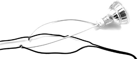
Figure 3-6: Connecting the lamp holder
For a more permanent connection, solder the twisted connection. Whether you solder them or not, wrap the connections in electrical tape. For a guide on how to make this kind of twisted-wire connection, see “Joining Wires by Twisting” on page 229.
STEP 2: WIRE UP THE FUSE AND SWITCH
Complete the wiring by attaching the fuse and alligator clip to the start of the wiring. Note that these MR16 light bulbs include a circuit to automatically switch the polarity of the LED. This means you can connect them either way around. If you use a different type of 12V LED, check whether it has separate positive and negative connections. If so, make sure that you connect the positive side to the switch lead and the negative side to the lead you’ll attach to the negative terminal on the battery.
The alligator clip attaches to the fuse lead, which is attached to the switch (Figure 3-7). Once again, these leads can be twisted together, and for a more reliable finish, you can solder the twisted joint. The in-line switch uses screw terminals to attach the wires. One side is just a metal connector that passes straight through, and the other side has spring contacts, which connect with each other when the switch is in the on position.
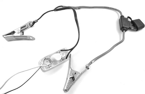
Figure 3-7: Connecting the fuse and alligator clip for a lighting system
STEP 3: INSTALL THE LAMPS
Now that everything is wired up, attach the alligator clips to the battery and make sure that the bulbs light when the switch is flicked. Once you know the lights turn on, just affix them to the ceiling, the wall, or wherever you want them.
USING THE LIGHTING
Murphy’s law dictates that batteries will run out of juice and shut off the lights just as the zombies attack. To anticipate and avoid this situation, it’s good to know roughly how many hours of light you’re going to get from your battery before you need to do some more pedaling or otherwise put some juice into it.
That number of hours depends on the size and quality of your battery. Looking back at Table 2-1 on page 21, you can see that a 5W LED is expected to last 120 hours. Therefore, a string of six 5W LEDs should be good for about 20 hours. If you go all out and put up a string of three 60W 12V halogen lamps, you’ll only get about 4 hours of light before needing another charge.
Whatever your lighting setup, it would be great to have advance notice that the battery is getting low—and this is the goal of the next project.
PROJECT 4: BATTERY MONITOR
I recommend keeping a good stock of car batteries charged up and ready to go at all times. That way, if zombies damage your solar panels, or you fall ill and can’t pedal your generator, you won’t be plunged into darkness and left powerless (in both senses of the word). It is therefore of paramount importance that you have an early warning system that will monitor the battery, telling you when it starts to get low so you can swap in a new one.
This project uses an Arduino, a useful little board that’s great for putting together electronic projects that require a bit of logic. In this case, the logic is simply to measure the battery voltage, display it, and sound a buzzer when it falls below a certain critical level.
The Arduino will be powered from the same car battery that it’s monitoring. The Arduino uses less than 1W to operate, so it’s okay to leave the board connected to the battery continuously.
In the battery monitor setup (Figure 3-8), alligator clips connect the battery monitor to the battery. If the battery has large alligator clips attached to it, then these smaller clips can be attached to the handles of the big clips.
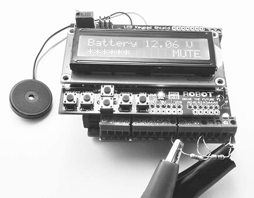
Figure 3-8: Battery monitor
The left lead of the left resistor (Figure 3-8) is connected to the positive battery terminal, and the right lead of the right resistor is connected to the negative battery terminal.
WHAT YOU WILL NEED
To make this project, you’ll need the following items.
ITEM
NOTES
SOURCE
Arduino Uno R3
Adafruit, Fry’s (7224833), Sparkfun
Screwshield
Adafruit (196)
LCD 16x2 display shield
eBay, Sparkfun (DEV-11851)
Small piezo buzzer
Adafruit (1740), eBay
Mouser (293-270-RC)
Mouser (293-470-RC)
Auto parts store
One great thing about using an Arduino is that there are many different ready-made modules, called shields, that fit on top of the Arduino and add extra features to it without any complex electronic construction. This project uses two such shields that are stacked on top of each other.
The first shield that fits on top of the Arduino is a screwshield, sometimes called a wing shield. This shield allows you to attach wires to the Arduino using screw terminals and a screw driver. The second and topmost shield that you’ll attach to the Arduino is an LCD display shield. This shield will tell you the battery level as a measurement of voltage and as a bar graph display of the state of charge (SOC) of the battery. The project also has an option to mute the buzzer to avoid attracting zombies, if you suspect they are shuffling about nearby.
The only other electronic components in this project are a pair of resistors and a buzzer. The resistors are needed because although the Arduino has inputs to measure voltage, it can only measure voltages up to 5V. Any more than that would damage the Arduino. You’ll use the pair of resistors in an arrangement called a voltage divider. The resistors I’ve chosen for my divider reduce the voltage to the Arduino by a factor of 2.74 so that the 12V or 13V that we might find at the battery will be reduced to 4.7V or less.
VOLTAGE DIVIDERS
Using two resistors as a voltage divider (Figure 3-9) is a great way to reduce the voltage you are trying to measure to a level where it can be directly measured by, say, an Arduino.
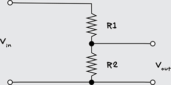
Figure 3-9: Voltage divider
The formula to calculate Vout if you know Vin, R1, and R2 is