For example, if R1 is 470 Ω, R2 is 270 Ω, and the maximum voltage of Vin is 13V, then
In other words, even if your battery is fully charged and managing to provide 13V, only a maximum of 4.74V (below the critical 5V level) will find its way to the Arduino. If the input voltage is lower than this, then Vout will scale proportionally. For example, if the battery voltage is 6.5V (which would indicate a bit of a problem, by the way), Vout would be 2.37V.
CONSTRUCTION
Remarkably, no soldering at all is needed to make this project. The only tool you need is a screwdriver.
STEP 1: PROGRAM THE ARDUINO
Arduino programs, which are called sketches, can change whether a connection, or pin, on the Arduino is an input or an output. The Arduino remembers whether each pin was set to input or output, even after you disconnect it from the rest of the circuit. Thus, if one of your Arduino pins was an output the last time you used it, connecting the Arduino to new hardware that expects the pin to be an input could damage the Arduino or the circuit you’re connecting it to. By uploading the program to the Arduino before doing anything else, you’ll ensure that each pin functions the way your circuit expects it to.
You’ll find detailed instructions on getting started with the Arduino, connecting it to your computer, and uploading a sketch to it in Appendix B. In this case, the sketch is called Project_04_Battery_monitor and can be found with all the other program files used in this book at http://nostarch.com/zombies/.
STEP 2: BUILD THE ARDUINO SANDWICH
When used with the two shields, the Arduino Uno is on the bottom, the screwshield is plugged into that, and, finally, the LCD display shield goes on top of the screwshield (Figure 3-10). The LCD shield has to be at the top of the stack or you won’t be able to see what it says!
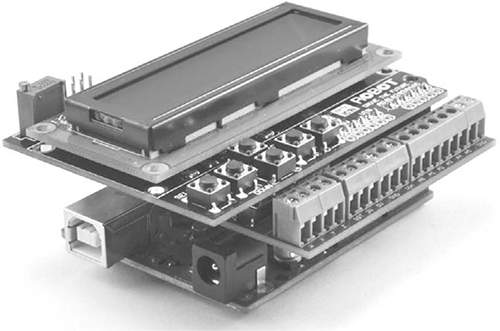
Figure 3-10: An Arduino “sandwich”
When pushing the pins of a shield into an Arduino or the screwshield, be careful to check that all the pins meet the holes correctly so you don’t damage them. It’s quite easy for one of the pins to splay out as you are pushing the pins in.
STEP 3: ATTACH THE RESISTORS AND BUZZER
You’ll attach the resistors and buzzer to the screw terminals of the screwshield (Figure 3-11).
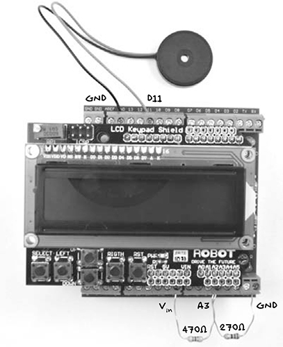
Figure 3-11: Connecting components to the screwshield
The two resistors can be identified either by measuring their resistance using a multimeter (see “Using a Multimeter” on page 237) or by reading the colored stripes on the resistor body. The 470 Ω resistor will have stripes of yellow, purple, and brown; the 270 Ω resistor will have red, purple, and brown stripes. In “Resistor Color Codes” on page 225, you will find a resistor color code table and instructions on how to identify resistors by their stripes.
Some buzzers will have a positive red lead and a negative black lead. If this is the case, connect the black lead to GND (ground) and the red lead to D11 on the Arduino. Other buzzers will have identical leads; if this is the case, it doesn’t matter which way around they are connected.
SOFTWARE
The sketch for this program is mostly concerned with making sure that the right text is displayed on the LCD at the right time. I’ll walk you through it in full, though you don’t have to understand or follow how this sketch works to finish the project. You can just upload it exactly as it is into the Arduino board, following the steps explained in “Installing the Antizombie Sketches” on page 248.
If you want to learn more about Arduino programming, see Appendix C or take a look at my book Programming Arduino: Getting Started with Sketches (McGraw-Hill, 2012).
The sketch starts by importing the LiquidCrystal library, which is responsible for controlling the LCD shield. Because this library is included as a standard part of the Arduino software, there is nothing to download and install for this library.
#include <LiquidCrystal.h>
After the library command, three constants are defined for key battery voltages.
const float maxV = 12.6;
const float minV = 11.7;
const float warnV = 11.7;
These voltages are, in order, the fully charged battery voltage, the minimum voltage that you want the battery to be allowed to discharge to, and the voltage at which the buzzer should sound. These last two are both set to 11.7V. These values are pretty standard for a lead-acid car battery, but if you use a different type of battery, you can tweak them. Because they hold decimal values, the variables are of a type called float. You can find out more about Arduino data types in Appendix C.
The next few lines define constants for the Arduino pins that are used.
const int buzzerPin = 11;
const int voltagePin = A3;
const int backlightPin = 10;
const int switchPin = A0;
The Arduino’s various pins are normally identified simply by a number, so these constants give them meaningful names. You don’t need to change these pin designations unless you decide to wire up your battery monitor differently.
The final section defines constants for the values of the resistors used in the potential divider.
const float R1 = 470.0;
const float R2 = 270.0;
const float k = (R1 + R2) / R2;
The constant k is the resulting factor the input voltage will be reduced by in order to fit into the 5V measurement range of the Arduino. The next line of code initializes the LCD display, specifying which pins are used.
// RS,E,D4,D5,D6,D7
LiquidCrystal lcd(8, 9, 4, 5, 6, 7);
boolean mute = false;
The comment line starting with // just identifies which of the Arduino pin numbers on the line beneath it correspond to which pins on the LCD module. The line after that defines a Boolean (a value that can be true or false) variable, mute, which is used to mute the buzzer.
The setup function that comes next is run just once, when the Arduino starts. In this case, it begins by setting the backlight pin (D10) to be an input.
void setup()
{
// Because of a defect in common cheap LCD displays,
// backlight controlled by transistor D10 high can
// burn out Arduino pin
pinMode(backlightPin, INPUT);
lcd.begin(16, 2);
lcd.setCursor(0, 0);
lcd.print("Battery ");
}
The backlight pin is used only on some LCD shields, but a significant number of LCD shields have a design flaw that can destroy the Arduino they are connected to if this pin is set to an output and also set high. To be on the safe side, D10 is set to an input. The rest of the function initializes the LCD display and writes out the word Battery, which will be a permanent fixture of the message displayed.
The loop function that follows the setup function is run repeatedly. That is, as soon as all the commands in the function have been executed, the function will start again from the top.