Figure 4-11: PIR lead and terminal block
I harvested my three-lead cable from a telephone extension lead. The cable contained four solid-core insulated wires. These wires were color coded, so I used blue for GND (ground), orange for 5V, and stripy white for the output; I left the final wire unused. The lead was about 30 feet (9 m) long, which worked fine for the sensor. You can probably use longer leads, but try it out first before you lay all the cabling.
STEP 3: CONNECT THE PIR TO THE SCREWSHIELD
Now that you’ve extended your sensor wires to a useful length, attach the wires to the Arduino screwshield (Figure 4-12; note that the two resistors from Project 4 are shown at the bottom left).
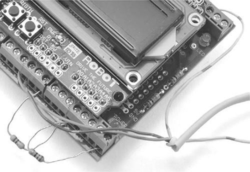
Figure 4-12: Connecting the PIR lead to the Arduino screwshield
If you look at the back of the PIR sensor, you’ll see that the three pins are labeled GND, OUT, and +5V. Connect GND on the PIR sensor to one of the GND connections on the screwshield; it doesn’t matter which one. Then, connect +5V on the PIR sensor to the 5V connection on the screwshield. Finally, connect OUT on the PIR sensor to D2 on the screwshield.
SOFTWARE
If you just want to make this project on its own, without any of the earlier Arduino-based projects, then use the sketch Project_06_PIR_Alarm. On the other hand, if you’ve made one or more of the other Arduino projects and wish to include them, then use the sketch All_Sensors and change the constants at the top to select the projects that you have made.
The first few lines of the All_Sensors sketch are shown below:
/*
Any projects that you want to exclude from this program should have a
value of "false". That way, you will not get any false alarms because
of missing hardware.
*/
const boolean project4 = true; // Battery Monitor
const boolean project6 = true; // PIR Alarm
const boolean project10 = false; // Door Monitor
const boolean project11 = false; // Fire Alarm
const boolean project12 = false; // Temperature Monitor
In this case, only the battery monitor (Project 4) and PIR alarm (Project 6) are enabled. If you’ve made more of the projects, then change the value next to those projects from false to true. If you are working your way through this book in order, then the program should look as shown.
All the source code for this book is available from http://www.nostarch.com/zombies/. See Appendix C for instructions on installing the programs.
The PIR detector code follows the same pattern as Project 4, so for more information on how the program as a whole works, please refer to “Software” on page 57. Here, I’ll just describe the code specific to this project.
The first change to the earlier code is the addition of a new constant for the PIR’s OUT pin. I added the pirPIN constant on the line after the switchPin constant.
const int pirPin = 2;
I set pirPin to 2 because the output of the PIR sensor will be connected to pin 2 on the Arduino. The next addition to the sketch occurs in the setup function, where that same pin 2 is set to be an input.
pinMode(pirPin, INPUT);
Although pins on an Arduino default to inputs unless specified as outputs, declaring the pin to be an input makes the code easier to follow.
The loop function now needs to check the sensor, so I added a call to the function checkPIR.
checkPIR();
This new function, checkPIR, will, as the name suggests, check the PIR sensor and take the appropriate action if the sensor is triggered. The function is defined right at the end of the sketch.
void checkPIR()
{
if (digitalRead(pirPin))
{
alarm("ZOMBIES!!");
}
}
The checkPIR function makes a digitalRead of the pirPin to decide whether the output from the PIR detector is HIGH or LOW. If movement has been detected, then the alarm function is used to display an appropriate message. For more information on using the inputs and outputs of an Arduino, see Appendix C.
USING THE PIR ZOMBIE DETECTOR
The project works well in combination with the battery monitor, as you can just run both off the same battery. But whether you combine the two projects or not, be mindful of your wires when you deploy the PIR detector around your base of operations. If you’re using cable that contains solid-core wires, then affix the cable to the wall at regular intervals along the cable length. Solid-core wires don’t take kindly to being repeatedly flexed.
SCAVENGED PIR SENSORS
The Adafruit PIR module used in this project is designed to work with microcontroller modules like the Arduino. But following an apocalypse, you may find it easier to obtain the type of regular PIR sensor intended for use with a security system, such as the unbranded unit obtained from eBay for a couple of dollars, shown opened up in Figure 4-13.
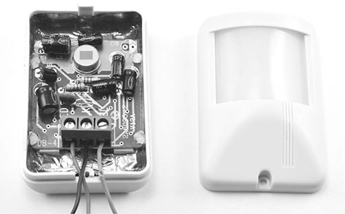
Figure 4-13: A PIR module intended for intruder alarms
This sensor won’t operate at 5V but rather requires a power supply of 12V. The sensor has a logic level output that will rise to 3.6V, which is enough to register as HIGH, just like the Adafruit module. The only difference in wiring is to connect this sensor’s red wire to the Arduino’s Vin rather than to 5V.
Be aware that other sensors may look like this one but have a different output voltage. Some (with an open collector output) require a pull-up resistor (of, say, 1 kΩ) between the output and 5V on the Arduino. If the output of the sensor does not give a useful voltage when you wave your hand in front of it, then it almost certainly needs a pull-up resistor.
Other types of PIR sensors, especially those intended to control lighting, have a relay output. This output works just like a switch, closing when movement is detected. The schematics show how to connect three types of PIR modules to the Arduino (Figure 4-14).
Wherever possible, choose a device that you have documentation for so you don’t have to guess how its output works and how to wire it up.
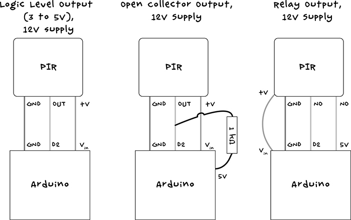
Figure 4-14: Connecting different types of PIR module to the Arduino
The next chapter advances from automatic zombie detection to walk through a number of surveillance projects that will allow you to see what is going on before it trips over your doorstep. You’ll be able to spot the zombies remotely using webcams.
5
SURVEILLANCE AND RASPBERRY PI

Now that you can detect zombies, it’s also a good idea to monitor their movements. But don’t risk joining the undead ranks by following them around! Watch them safely from inside your base, and you’ll keep your brain intact. This chapter shows you how to make a surveillance camera setup with USB and wireless webcams, using a Raspberry Pi single-board computer to minimize your energy usage (see Figure 5-1).
Both projects in this chapter require you to download software, so you’d be well advised to think ahead and get your system set up before disaster strikes.