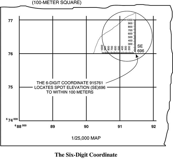
•Location of a point within 100 meters. Use the appropriate corner of a coordinate scale that breaks the 1,000-meter square into 10 equal parts along each side (100-meter segments are indicated by longer lines on the coordinate scale). Place the coordinate scale along the east-west grid at the lower left-hand corner of the grid square, then slide it eastward to the center of the object. Location is expressed as a six-digit coordinate. The third digit is the longer line nearest grid line 91, and the sixth digit is the longer line nearest the spot elevation (SE), e.g., 915761.
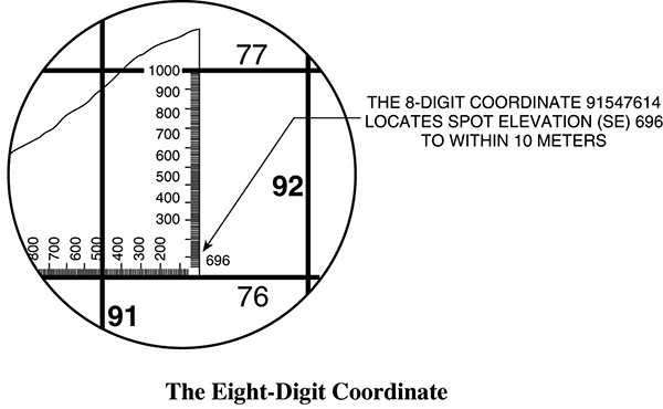
•Location of a point within 10 meters. The short lines divide 100-meter segments into 20-meter segments. To read to the nearest 10 meters, interpolate along the scale. The coordinate will be an eight-digit coordinate, e.g., 91547614.
Scale
Scale is defined as the fixed relationship between map distance (MD) and the corresponding ground distance (GD). It is expressed as a representative fraction (RF):
The RF appears in the margin of the map as 1/25,000 or 1:25,000, each of which means that 1 unit of measure on the map represents 25,000 similar units of measure on the ground.
The graphic scale is printed in the margin as a special ruler and is used to measure ground distances on a map. Military maps normally have three graphic scales, expressed in miles, meters, and yards.
Direction
Direction is defined as an imaginary straight line on the map or ground and is expressed as an azimuth.
Azimuth. An azimuth is a horizontal angle measured clockwise from a north baseline. All directions originate from the center of an imaginary circle called the azimuth circle. This circle is divided into 360 equal units of measurement, called degrees. The degrees are numbered in a clockwise direction, with east at 90 degrees, south at 180 degrees, west at 270 degrees, and north at 360 or 0 degrees. Distance has no effect on azimuth.
Back Azimuth. The back azimuth of a line differs from its azimuth by exactly 180 degrees. The rules for determining back azimuth are as follows:
•If the azimuth is less than 180 degrees, the back azimuth is the value of the azimuth plus 180.
•If the azimuth is more than 180 degrees, the back azimuth is the value of the azimuth minus 180.
•If the azimuth is 180 degrees, the back azimuth is 0 degrees or 360 degrees.
Measuring Azimuths on a Map. Map azimuths are measured with a protractor. The issue protractor (MR-1) is graduated in two scales—0 to 180 degrees, and 180 to 360 degrees—to represent the complete azimuth circle.
To read a map azimuth between any two points:
•Draw a line connecting the two points.
•Place the index at the point from which you are measuring, ensuring that the baseline of the protractor is on or parallel to a north-south grid line.
•Read the azimuth at the point where the line intersects the scale.
To plot an azimuth on a map:
•Place the protractor on the map with the index at the initial point and baseline parallel to a north-south grid line.
•Place a dot on the map at the desired azimuth reading.
•Remove the protractor; connect the initial point and the dot with a line.
Base Direction. There are three base directions: true north, grid north, and magnetic north.
1.True north. Direction to the north pole. The symbol is a star.
2.Grid north. Direction of the north-south grid lines. The symbol is GN.
3.Magnetic north. Direction in which the magnetic arrow of a compass points. The symbol is a half arrow.
The angular relationships among these three directions are shown by a declination diagram in the margin of a map.
Grid-Magnetic Angle
To understand the grid-magnetic (G-M) angle, you must know the meaning of azimuth. Map readers are concerned with two base directions: grid north, from which we read grid azimuths (protractor and map), and magnetic north, from which we read magnetic azimuths (compass and ground).
Grid azimuth is a horizontal angle measured clockwise from grid north.
Magnetic azimuth is a horizontal angle measured clockwise from magnetic north.
G-M angle is the angular difference between grid north and magnetic north, measured from grid north.
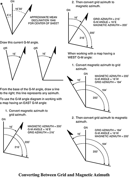
To use a grid azimuth in the field with a compass, you must first change it to a magnetic azimuth. To plot a magnetic azimuth on a map, you must first change it to a grid azimuth. To make either of these changes, you must use a G-M angle diagram as shown in the diagram.
You should construct and use the G-M angle diagram each time conversion of azimuths is required. As a time-saving procedure when working frequently with the same map, construct a G-M angle conversion table on the margin. The following is an example, using a map having a G-M angle of 16 degrees east:
For conversion of:
Magnetic azimuth to grid azimuth: Add 16 degrees
Grid azimuth to magnetic azimuth: Subtract 16 degrees
Intersection. Distant or inaccessible objects can be located on a map by intersecting lines from two known points. For example, a magnetic azimuth from a known observation post (OP) to a distant point is converted to a grid azimuth and drawn on the map. Another magnetic azimuth from another OP to the same distant point is converted to a grid azimuth and drawn on the same map. The intersection of the two lines on the map is the location of the known point.
Resection. The resection method lets you locate your position on a map. Take magnetic azimuths to two distant points on the ground that can be identified on the map. Change these azimuths to back azimuths, convert to grid azimuths, and draw the converted azimuths from the known points on the map. Your location is where these two lines intersect. To verify and make a final determination of your position, compare ground features with those shown on the map.
Modified Resection. Modified resection is a method of locating your position on a map when you are on a road, stream, or other linear feature identified on the map. Take a magnetic azimuth to a distant point that can be identified both on the ground and on the map. Change this to a back azimuth and convert to a grid azimuth. Draw this converted azimuth on the map from the known point. Your position is where the azimuth line on the map crosses or intersects the linear feature.
Elevation and Relief (Contour Lines)
On a standard topographical map, contour lines are the most common method of showing relief and elevation. A contour line represents an imaginary line on the ground, above or below sea level. All points on the contour line are at the same elevation. The elevation represented by contour lines is the vertical distance above or below sea level. The three types of contour lines used on a standard topographic map are as follows:
•Index. Starting at zero elevation or mean sea level, every fifth contour line is a heavier line. These are known as index contour lines. Normally, each index contour line is numbered at some point. This number is the elevation of that line.
•Intermediate. The contour lines falling between the index contour lines are called intermediate contour lines. These lines are finer and do not have their elevations given. There are normally four intermediate contour lines between index contour lines.