Platoons establish defensive positions in accordance with the platoon leader and commander’s plan. They mark EAs using marking techniques prescribed by unit SOP. The platoon physically marks obstacles, TRPs, targets, and trigger lines in the EA. During limited visibility, the platoon can use infrared light sources to mark TRPs for the rifle squads. When possible, platoons should mark TRPs with both a thermal and an infrared source so the rifle squads can use the TRP.
Range Cards. A range card is a sketch of a sector that a direct-fire weapons system is assigned to cover. A range card aids in planning and controlling fires and aids the crew in acquiring targets during limited visibility. It is also an aid for replacement personnel, platoons, or squads to move into the position and to orient on their sector. During good visibility, the gunner should have no problems maintaining orientation in his sector. During poor visibility, he may not be able to detect lateral limits. If the gunner becomes disoriented and cannot find or locate reference points or sector limit markers, he can use the range card to locate the limits. The gunner should make the range card so that he becomes more familiar with the terrain in his sector. Range cards are prepared immediately during stage 1 of defensive fighting positions (see Chapter 13) and are updated as necessary. Two copies of the range card are prepared, one for the position and one for the squad leader to prepare his sketch.
The range card has two sections: a sector sketch section and a data section. The marginal information at the top of the card is listed as follows:
•SQD, PLT, and CO. The squad, platoon, and company designations are listed. Units higher than company are not listed.
•Magnetic north. The range card is oriented with the terrain, and the direction of magnetic north arrow is drawn.
The gunner’s sector of fire is drawn in the sector sketch section. It is not drawn to scale, but the data referring to the targets must be accurate.
•The weapon symbol is drawn in the center of the small circle.
•Left and right limits are drawn from the position. A circled “L” and “R” are placed at the end of the left and right limit lines, respectively.
•The value of each circle is determined by using a terrain feature farthest from the position that is within the weapon’s capability. The distance to the terrain is determined and rounded off to the next even hundredth, if necessary. The maximum number of circles that will divide evenly into the distance is determined and divided. The result is the value for each circle. The terrain feature is then drawn on the appropriate circle.
•All TRPs and reference points are drawn in the sector. They are numbered consecutively and circled.
•Dead space is drawn in the sector.
•A maximum engagement line is drawn on range cards for antiarmor weapons.
•The weapon reference point is numbered last. The location is given a six-digit grid coordinate. When there is no terrain feature to be designated, the location is shown as an eight-digit grid coordinate.
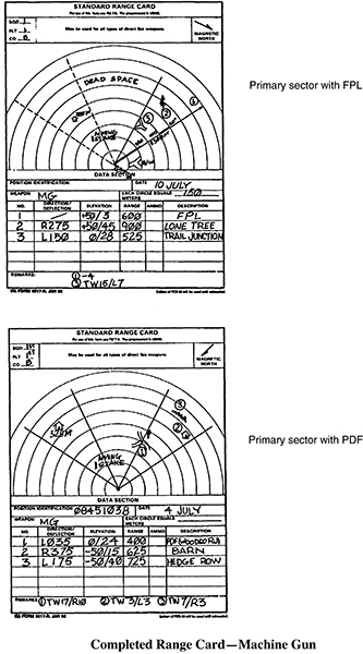
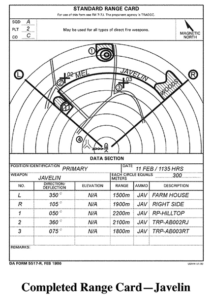
The data section is filled in as follows:
•Position identification. Identify the position as primary, alternate, or supplementary.
•Date. Enter the date and time the range card was completed.
•Weapon. The weapon block indicates the weapons used.
•Distance. Each circle equals meters. Write in the distance in meters between circles.
•No. Starting with left and right limits, list the TRPs and reference points in numerical order.
•Direction/deflection. List the direction in degrees and the deflection in mils.
•Elevation. List the elevation in mils.
•Range. List the distance in meters from the position to the left and right limits and TRPs and reference points.
•Ammo. List the type of ammunition used.
•Description. List the name of the object(for example, farmhouse, woodline, hilltop).
•Remarks. List the weapon reference point data and any additional information.
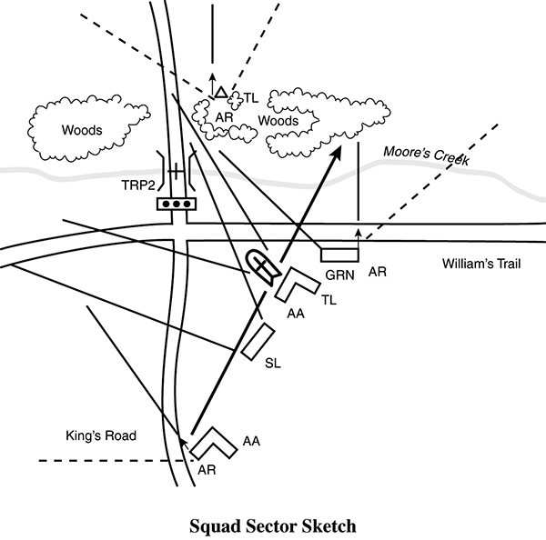
Sector Sketches. Leaders prepare sector sketches based on their defensive plan. They use the range card for each fighting position (prepared by the soldiers in each position). Detailed sketches aid in the planning, distribution, and control of the platoon fires. Squad leaders prepare squad sector sketches, section leaders prepare section sketches, and the platoon leader prepares the platoon sketch.
Squad Sector Sketch. Each squad leader prepares a sector sketch to help him plan his defense and control fire. The squad leader prepares two copies of the sector sketch. He gives one to the platoon leader and keeps the second at his position. The SOP should state how soon after occupying the position the leader must forward the sketch. The sketch shows the following:
•Squad and platoon identification.
•Date/time group.
•Magnetic north.
•The main terrain features in his sector of fire and the ranges to them.
•Each primary fighting position.
•Alternate and supplementary positions.
•The primary and secondary sectors of fire of each position.
•Maximum engagement line.
•Machine-gun FPLs or PDF.
•Dragon positions with sectors of fire.
•The type of weapon in each position.
•Observation posts and the squad leader’s position.
•Dead space to include coverage by grenade launchers.
•Location of night vision devices (NVGs).
•Obstacles, mines, and booby traps.
Platoon Sector Sketch. The platoon leader checks range cards and squad sector sketches. If he finds gaps or other flaws in his fire plan, he adjusts the weapons or sectors as needed. If he finds any dead space, he takes steps to cover it with mines, grenade-launcher fire, or indirect fire. He then makes two copies of his platoon sector sketch—one for his use and the other for the company commander. His sketch shows the following:
•Squad sectors of fire.
•Machine-gun and antiarmor weapon positions and their sectors of fires, including FPLs and PDFs of the automatic rifles and machine guns and TRPs for the antiarmor weapons.
•MELs for antiarmor weapons.
•Mines (Claymores) and obstacles.
•Indirect fire planned in the platoon’s sector of fire (targets and FPF).
•OPs and patrol routes, if any.
•Platoon CP.
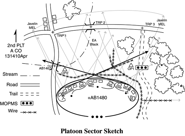
•Platoon/company identification.
•Date/time group.
•Magnetic north.
•Location of CCP.
•Location of NVDs/thermal sights that are part of the limited-visibility security plan.
•Adjustments during limited visibility to maintain coverage of assigned TRPs.
Establishment of Command Post and Wire Communications
The platoon CP is set up where the platoon leader can best see and control his platoon. If he cannot see the entire platoon sector from one place, he sets up where he can see and control the main effort. He then sets up an alternate CP where the platoon sergeant can see and control the rest of the platoon.
In the defense, the platoon CP ties in to the company wire net with a field telephone. Wire is the primary means of communications between the platoon leader and squad leaders. The platoon has its own radio net, and the platoon leader also uses messengers, visual signals, personal contact, or whistles to communicate.